Apparatus and method employing retrievable landing base with guide for same location multiple perforating gun firings

a perforating gun and landing base technology, applied in the field of perforating guns, can solve the problems of inability to provide a deep and large diameter penetration at the same point, inability to bypass formation damage, and current perforation practices that cannot provide the same depth of penetration, etc., and achieve the effect of better penetration

Active Publication Date: 2020-06-09
SAUDI ARABIAN OIL CO
View PDF33 Cites 0 Cited by
  • Summary
  • Abstract
  • Description
  • Claims
  • Application Information

AI Technical Summary

Benefits of technology

[0015]The perforating gun assembly includes a guide member that is dimensioned and configured to mate with the receiving member of the landing base assembly. The guide member is secured to the perforating gun in axial alignment with its longitudinal axis. A rotating head member is secured in axial alignment to the top or upper end of the perforating gun. The perforating gun remains attached by the rotating head to the coiled tubing when the gun assembly is downhole and is only released from the end of the coiled tubing at the surface in order to remove a gun that has been fired and load another gun with the same charge configuration. After securing a loaded gun to the coiled tubing, the gun assembly is lowered into engagement with the receiving member. The rotating head member permits relative rotational movement of the perforating gun and attached guide member, as will be described in more detail below, in order to facilitate the mating of the landing base assembly and the perforating gun assembly in preparation for firing.
[0028]It will also be understood that the new landing base assembly of the present disclosure functions to by-pass the near-wellbore damaged zone and can provide better penetration of more than one casing by same location repeated reservoir penetrations when the well is not equipped with the latch coupling system, such as is described in U.S. Pat. No. 9,506,330, “System and Method Employing Perforating Gun for Same Location Multiple Reservoir Penetrations”.

Problems solved by technology

However, if the perforation plan for the well is changed so that a perforation is to be performed at a lower depth, or further into a lateral / horizontal open hole wellbore, the accuracy at the new depth of a perforation at the same point will be jeopardized.
Current perforation practices can fail to provide a deep and large diameter penetration when the target zone is behind more than one casing.
A problem also exists in formations with high compressive strength and can also fail to bypass formation damage caused by the explosive forces.
A problem to be solved then is to provide apparatus, systems and methods in preparation for hydraulic fracturing operations that operate without a rig for securely positioning a perforating gun at the desired location for the first of a planned series of firings and returning the gun after reloading at the surface to the same position and radial orientation for one or more firings to complete a plurality of reservoir perforations or penetrations to the same position in order to produce a deep penetration having a larger diameter than is currently possible.
An additional problem to be addressed is maintaining the accuracy of the perforation when the perforation plan includes at least an additional perforation interval at a position in the wellbore that is displaced, e.g., beyond, the first perforation interval.

Method used


Image

  • Apparatus and method employing retrievable landing base with guide for same location multiple perforating gun firings
  • Apparatus and method employing retrievable landing base with guide for same location multiple perforating gun firings
  • Apparatus and method employing retrievable landing base with guide for same location multiple perforating gun firings

Examples


Embodiment Construction

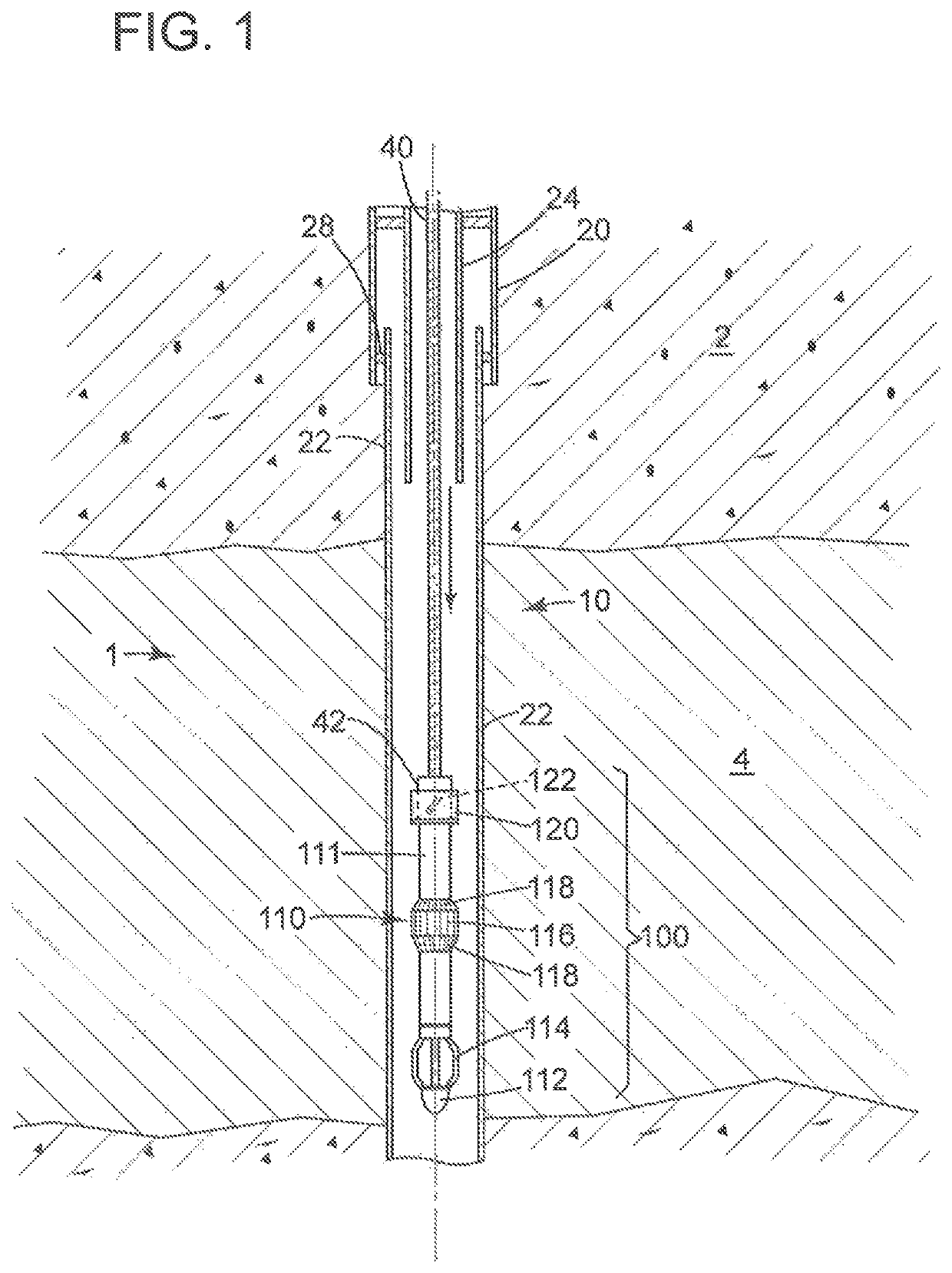
[0044]Referring now to the schematic illustration of FIG. 1, there is shown a downhole portion 1 of wellbore 10 in a section of reservoir rock 2 in a tight formation in which hydraulic fracturing is required to enhance gas production. It is to be understood that the region 2 above the hydrocarbon containing interval of reservoir rock 4 in a tight formation can extend for thousands of feet from the earth's surface before reaching the interval at which hydrofracking is required. As shown in FIG. 1, the final section of well liner 22 is secured in position by packers 28 at the end of well casing 20. Liner 22 extends beyond the end of the production tubing 24 and terminates below the hydrocarbon containing interval 4. As also shown in FIG. 1, production tubing 24 terminates in the well liner above the interval to be perforated.

[0045]With continuing reference to FIG. 1, a through-tubing retrievable bridge plug 110 is shown suspended in the region below, but proximate to the interval that...


PUM


Abstract

Methods and apparatus are provided for conducting multiple successive same-location firings of a number of shaped charges carried by a perforating gun that is lowered into the wellbore and precisely positioned by engagement with a landing base assembly that includes a through-tubing retrievable bridge plug to which is secured a receiving member that matingly engages a perforating gun assembly that includes a mating guide member secured to the downhole end of the perforating gun and a rotating head member attached to the opposite upper end of the gun, the rotating head member configured for attachment to the downhole end of a length of coiled tubing for lowering the gun assembly and permitting its axial rotation and downward vertical movement into a final secure, but releasably engaged position with the fixed landing base assembly. The landing base assembly can be recovered via the production tubing using a wire line or coiled tubing following the multiple reservoir penetration firings by retraction of the locking anus of the bridge plug to their original collapsed position.

Description

FIELD OF THE INVENTION[0001]This invention relates to the use of perforating guns, that can be positioned without the use of a surface rig for multiple same location perforations of tight reservoir formations, e.g., deep penetrations in preparation for the hydraulic fracturing of the formation.BACKGROUND OF THE INVENTION[0002]Tight gas formations, such as Khuff carbonate, pre-Khuff sandstone and shale gas formations with high compressive strength require hydraulic fracturing procedures in order to open the reservoir formation and enhance the flow of gas to the well bore for production. In such tight gas-containing reservoir formations, a perforating gun is used to initiate formation breakdown by detonating high-performance deep-penetrating shaped charges that maximize perforation length and entry hole size to start the hydraulic fracturing or “hydrofracking”, in order to enhance hydrocarbon production and optimize well flow.[0003]The tubing-conveyed perforating (TCP) gun employs a d...

Claims


Application Information

Patent Timeline
Patent Type & Authority Patents(United States)
IPC IPC(8): E21B43/11E21B43/117E21B43/1185E21B43/119E21B47/024
CPCE21B43/119E21B43/11855E21B43/117E21B47/024
Inventor AL-GOUHI, ALWALEED A.
Owner SAUDI ARABIAN OIL CO
Why Eureka
Try Eureka