Spinner Aft-Extended Forward Return Flange

a forward return and spinner technology, applied in the direction of efficient propulsion technologies, machines/engines, combustion air/fuel air treatment, etc., can solve the problems of unnecessary, added spinner weight, and unnecessary weight, and achieve the effect of facilitating the mating of the nosecap

Active Publication Date: 2016-02-04
RTX CORP
View PDF18 Cites 0 Cited by
  • Summary
  • Abstract
  • Description
  • Claims
  • Application Information

AI Technical Summary

Benefits of technology

[0024]In a refinement, the spinner may include geometry to facilitate mating the nosecap with the forward flange.

Problems solved by technology

The use of a metallic ring in place of a return flange may improve foreign object resistance, but may also add unwanted cost for production.
Further, a metallic ring at the forward end of the spinner may add unnecessary, excess weight to the spinner.

Method used


Image

  • Spinner Aft-Extended Forward Return Flange
  • Spinner Aft-Extended Forward Return Flange
  • Spinner Aft-Extended Forward Return Flange

Examples


Embodiment Construction

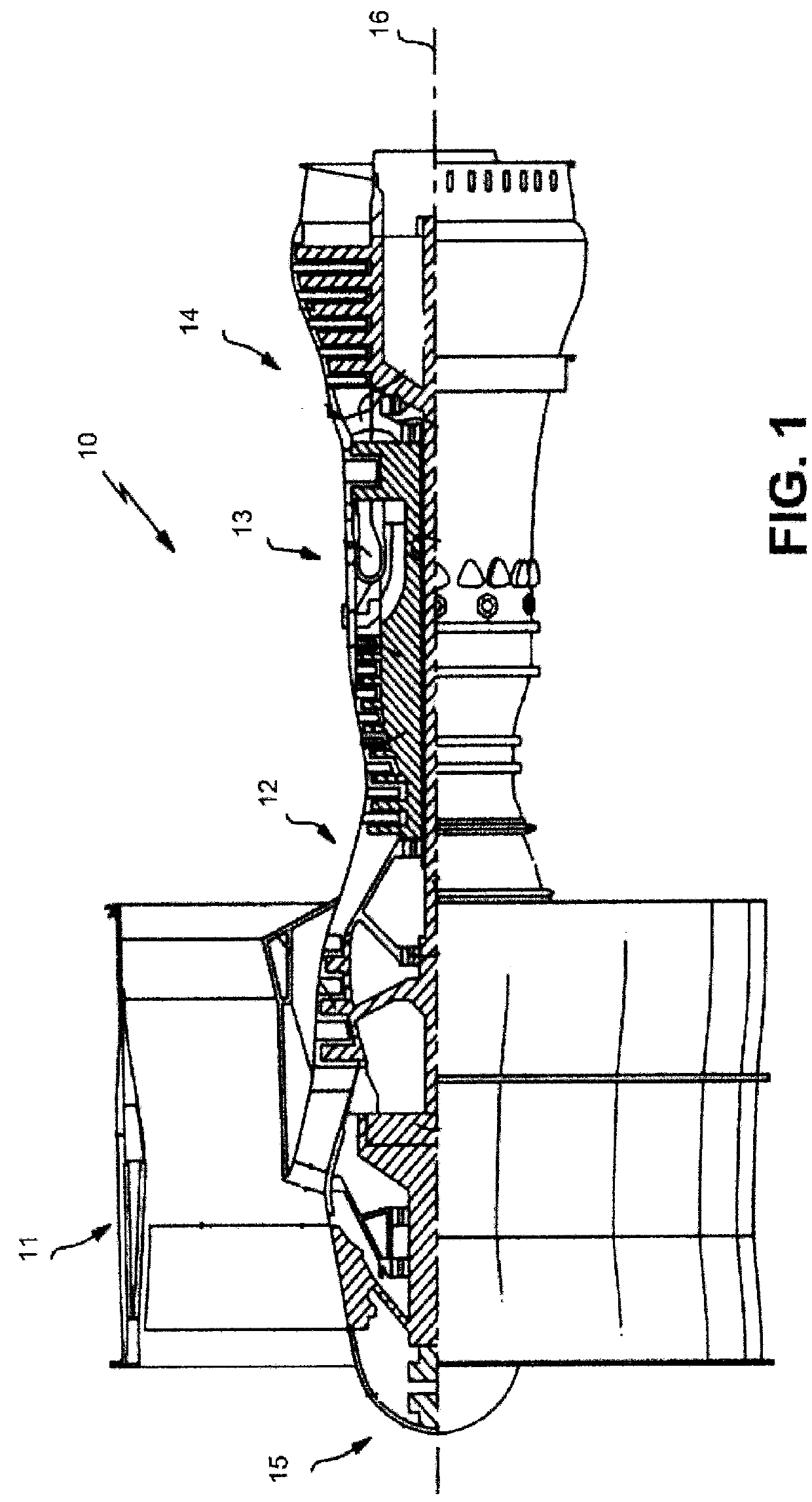
[0035]Referring to the drawings, and with specific reference to FIG. 1, a gas turbine engine constructed in accordance with the present disclosure is generally referred to by reference numeral 10. Such a gas turbine engine 10 can be used for any number of different applications including, but not limited to, generation of aircraft thrust and land-based power. Moreover, it is to be understood that the sectional view provided in FIG. 1 is included simply to provide a basic understanding of the various sections in a gas turbine engine, and not to limit the invention thereto. The present disclosure extends to all types of gas turbine engines used in all types of applications.

[0036]The gas turbine engine 10 may have a fan section 11, the fan section 11 drawing in ambient air and directing the ambient air to a compressor section 12. The incoming air is greatly compressed by the compressor section 12 and directed to a combustor section 13 where it is mixed with fuel and combusted. The prod...


PUM

PropertyMeasurementUnit
circumferenceaaaaaaaaaa
impact forcesaaaaaaaaaa
durabilityaaaaaaaaaa

Abstract

A spinner for a fan assembly of a gas turbine engine, a method of fabricating a spinner for a fan assembly of a gas turbine engine, and a gas turbine engine are disclosed. The fan section may include a nosecap. The spinner may include a forward end, an aft end, and a return flange associated with the forward end. The return flange may include a forward flange extending forward towards the nosecap and an aft flange extending aft towards the aft end.

Description

TECHNICAL FIELD OF THE DISCLOSURE[0001]This application claims priority under 35 USC § 119(e) to US Provisional Patent application Ser. No. 62 / 030,931 filed on Jul. 30, 2014.BACKGROUND OF THE DISCLOSURE[0002]In a gas turbine engine, the spinner of the fan section is designed to direct local flow into the root of the fan blades. The spinner may be designed to minimize foreign object damage, such as impact forces caused by hail and bird strikes. Additionally, the spinner may be designed to minimize bill of material object damage, which is damage caused by components of the engine itself. Per Federal Aviation Administration (FAA) regulations, the gas turbine engine must be designed to meet given continued operation requirements after foreign object strikes to the fan, including the spinner. Additionally, increased durability of the gas turbine engine and the spinner itself is beneficial to the owner because the reduced wear and tear on the engine may contribute to lower repair costs an...

Claims


Application Information

Patent Timeline
Patent Type & Authority Applications(United States)
IPC IPC(8): F02C7/04B29C43/02F02C3/04
CPCF02C7/04F02C3/04B29C43/021F05D2220/32F05D2300/43B29L2031/7504F05D2240/35F05D2230/30B29C2043/026B29K2101/00F05D2240/20F05D2220/36Y02T50/60B64C11/14
Inventor KLING, COLIN J.LUSSIER, DARIN S.
Owner RTX CORP
Why Eureka
Try Eureka