
Liquid discharge apparatus with wiper cleaner

a technology of liquid discharge apparatus and wiper cleaner, which is applied in the direction of printing, etc., can solve the problems of wiper or the upper part of the wiper cleaner being practically undeformable, and the wiper or the wiper cleaner being liable to get damaged, etc., to regulate and reduce the deformation of the wiper

Active Publication Date: 2016-12-13
BROTHER KOGYO KK
View PDF17 Cites 1 Cited by
  • Summary
  • Abstract
  • Description
  • Claims
  • Application Information

AI Technical Summary

Benefits of technology

The invention is about a wiper cleaner that prevents wipers from getting caught or scratched while still maintaining cleaning accuracy. The cleaner has a slit that is designed to catch the wiper, but it is narrow enough to prevent the wiper from passing through smoothly. To solve this problem, the patent proposes a design that allows the wiper to be easily inserted into the cleaner space, which regulates the bending and deformation of the wiper. This way, the wiper can pass through the slit smoothly while still getting caught.

Problems solved by technology

The above ink-jet printer, however, has the following problems.
This prevents the wiper from passing through the slit smoothly, and further the wiper or the wiper cleaner is liable to get damaged.
Further, the upper part of the wiper cleaner is practically undeformable, because the wiper cleaner is accommodated in the support member with the upper part of the wiper clear compressed.
Thus, when the wiper having flexibility is inserted into the slit of the wiper cleaner, the wiper may be caught or scratched by the slit.
Thus, when the wiper is inserted into the slit of the wiper cleaner, the front end of the wiper may be caught or scratched by the entrance of the slit of the wiper cleaner.
This prevents the wiper from passing through the slit smoothly, and the wiper or the wiper cleaner is liable to get damaged.

Method used


Image

  • Liquid discharge apparatus with wiper cleaner
  • Liquid discharge apparatus with wiper cleaner
  • Liquid discharge apparatus with wiper cleaner

Examples


first embodiment

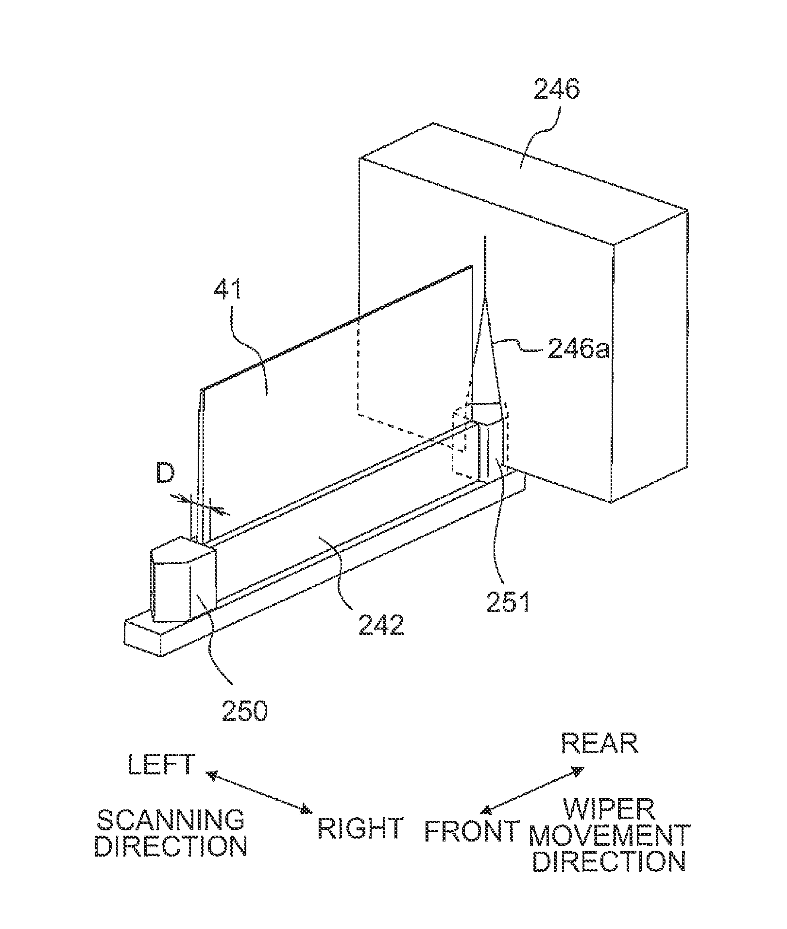
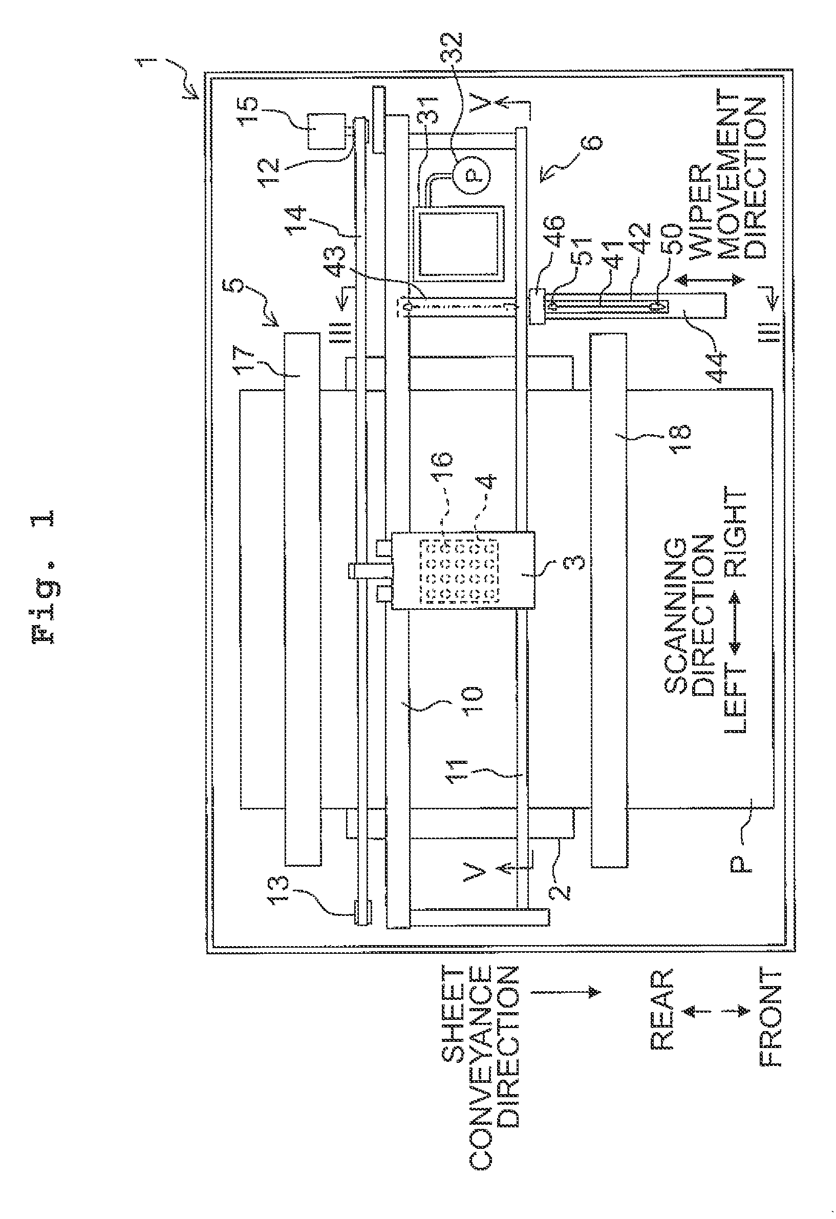
[0110]The wiper 41 is thin, of which entire thickness is, for example, about 1 mm. The upper end of the wiper 41 is in a tapered shape. This allows the wiper 41 to bend easily when the wiper 41 makes contact with the ink discharge surface 4a, and thereby making it possible to wipe off the ink on the ink discharge surface 4a reliably. When the restoring force or resilience, by which the wiper 41 in the bent state is restored to a normal state, is great, the force, which is transmitted from the wiper 41 to the water-repellent film covering the ink discharge surface 4a, is also great. In the first embodiment, however, since the wiper 41 has the thickness of approximately 1 mm, the resilience is relatively small. This reduces the force transmitting from the wiper 41 to the water-repellent film, and thereby making it possible to prevent the water-repellent film from peeling off.

[0111]The wiper holder 42 includes two space expansion parts 50, 51 which are disposed on the front and rear si...

second embodiment

[0155]The upper end of the wiper 1041 is positioned above the ink discharge surface 4a. As depicted in FIG. 20C and FIG. 20D, when the ink-jet head 4 in the maintenance position moves in the scanning direction (in particular, leftward) with the wiper 1041 being in the wiping position, the ink adhering to the ink discharge surface 4a of the ink-jet head 4 is wiped with a right surface 1041s1 (a first surface of the present teaching) of the wiper 1041. In the second embodiment, a carriage drive motor 15 corresponds to a second movement mechanism of the present teaching. The ink wiped is more likely to adhere to the right surface 1041s1 of the wiper 1041, and is less likely to adhere to a left surface 1041s2 (a second surface of the present teaching). The length of the wiper 1041 in the front-rear direction is substantially the same as or longer than the length of the ink discharge surface 4a in the front-rear direction. The wiper 1041 can wipe the entire ink discharge surface 4a durin...

third embodiment

[0202]The wiper 2041 is thin, of which entire thickness is, for example, about 1 mm. The upper end 2041u of the wiper 2041 is in a tapered shape. This allows the wiper 2041 to bend easily when the wiper 2041 makes contact with the ink discharge surface 4a, and thereby making it possible to wipe off the ink on the ink discharge surface 4a reliably. When the restoring force or resilience, by which the wiper 2041 in the bent state is restored to a normal state, is great, the force, which is transmitted from the wiper 2041 to the water-repellent film covering the ink discharge surface 4a, is also great. In the third embodiment, however, since the wiper 2041 has the thickness of approximately 1 mm, the resilience is relatively small. This reduces the force transmitting from the wiper 2041 to the water-repellent film, and thereby making it possible to prevent the water-repellent film from peeling off.

[0203]The wiper cleaner 2046 is held by a cleaner holder 2047 and is disposed between the...


PUM


Abstract

There is provided a liquid discharge apparatus, including: a liquid discharge head; a wiper; a wiper cleaner cleaning a liquid adhering to a first surface of the wiper and including a first contact part, which makes contact with the first surface of the wiper, and a second contact part, which is disposed to face the first contact part and makes contact with the second surface of the wiper; a movement mechanism moving the wiper and the wiper cleaner relative to each other, and a space expansion part expanding a space between the first contact part and the second contact part.

Description

CROSS REFERENCE TO RELATED APPLICATION[0001]The present application claims priorities from Japanese Patent Application Nos. 2014-202443, 2014-202544, 2014-202545, and 2014-202546 filed on Sep. 30, 2014, the disclosures of which are incorporated herein by reference in its entirety.BACKGROUND[0002]Field of the Invention[0003]The present teaching relates to a liquid discharge apparatus which discharges liquid.[0004]Description of the Related Art[0005]As a liquid discharge apparatus which discharges liquid onto a discharge target medium from liquid discharge ports formed on a liquid discharge surface of a liquid discharge head, there is known an ink-jet printer which performs printing on a recording sheet by discharging ink from an ink-jet head. The ink-jet printer wipes off foreign matters, such as ink adhering to an ink discharge surface, with a wiper made of rubber and the like. For example, the ink-jet printer may include a wiper cleaner being made of sponge and the like and having ...

Claims


Application Information

Patent Timeline
Patent Type & Authority Patents(United States)
IPC IPC(8): B41J2/165
CPCB41J2/16541B41J2/16538
Inventor KUNO, DAISUKEHIGUCHI, RIE
Owner BROTHER KOGYO KK
Learn More