Draper platform with center section and lateral sections arranged laterally to the center section

a draper platform and lateral section technology, applied in the field of draper platforms, can solve the problems that the spacing of pivotable arms within the area of the center section and the lateral sections of the draper platform must not be uniform everywhere, and achieve the effects of reducing the number of pivotable arms, reducing the number of stiffness, and maintaining the ground adaptation capability of the cutter bar

Active Publication Date: 2016-12-27
CARL GERINGHOFF GMBH & CO KG
View PDF16 Cites 7 Cited by
  • Summary
  • Abstract
  • Description
  • Claims
  • Application Information

AI Technical Summary

Benefits of technology

[0005]By reducing the number of arms, the weight of the draper platform as a whole is lowered; also, its manufacturing costs can be reduced. For example, in case of a draper platform with 10 m working width, a lateral spacing of the pivotable arms of 1 m relative to each other, and two stationary arms on the exterior sides, only nine such arms can be sufficient in order to copy with the cutter bar the contour of the ground of a field to be harvested while in the device according to the prior art twelve such arms would be required. For a spacing of the pivotable arms relative to each other of 1.5 m, six pivotable arms instead of twelve would be sufficient: this corresponds to cutting in half the number of arms. Due to the reduced number of pivotable arms, the draper platform becomes much lighter for identical working width, in particular also the lateral sections, so that the expenditure for compensating the carrying forces for the lateral sections on the central section of the draper platform as well as on the holders relative to and on the feed conveyor of the harvesting machine is reduced also. Surprisingly, the ground adaptation of the cutter bar relative to the ground contour is hardly deteriorating because the theoretically possible pivot travel of the pivotable arms in the arrangement according to the prior art is limited by the limited flexibility of the cutter bar.
[0007]According to one embodiment of the invention, the cutter bar is provided across its working width with different stiffness. Due to the different stiffness, individual sections of the cutter bar of a softer design can deform more strongly than other sections that are stiffer. In this way, it is possible to maintain the ground adaptation capability of the cutter bar, despite the reduced number of pivotable arms, at a level comparable to the prior art in that due to the different stiffness of the cutter bar across its working width height differences can also be compensated at least partially by the cutter bar itself without a corresponding pivoting action of the pivotable arms in the height direction. Also, the areas of the cutter bar that are less stiff enable the pivotable arms to move more easily across the theoretically possible pivoting stroke. Accordingly, individual pivotable arms can carry out greater pivot travels without thereby at least partially entraining neighboring pivotable arms or the entrainment movement is significantly shorter in comparison to a cutter bar that is embodied with uniform stiffness because a portion of the entrainment movement is compensated by the more flexible sections of the cutter bar.
[0008]According to one embodiment of the invention, a cutter bar section between two neighboring pivotable arms is embodied in its central area more stiffly than in its lateral areas. Due to the stiffer configuration of the central area, this area will sag less strongly in downward direction than a less stiff configuration. Accordingly, the cutting pattern of the stubble on the field is less wavy than in the case without stiffening. The reduced bending stiffness in the lateral areas permits on the other hand a stronger bending movement of this cutter bar section as a whole so that the adaptation movements of the cutter bar relative to a changing ground contour, as the harvesting machine advances into the crop stand, are facilitated.

Problems solved by technology

Surprisingly, the ground adaptation of the cutter bar relative to the ground contour is hardly deteriorating because the theoretically possible pivot travel of the pivotable arms in the arrangement according to the prior art is limited by the limited flexibility of the cutter bar.
In this context, the spacing of the pivotable arms within the area of the center section and of the lateral sections of the draper platform must not be uniform everywhere.

Method used


Image

  • Draper platform with center section and lateral sections arranged laterally to the center section
  • Draper platform with center section and lateral sections arranged laterally to the center section
  • Draper platform with center section and lateral sections arranged laterally to the center section

Examples


Embodiment Construction

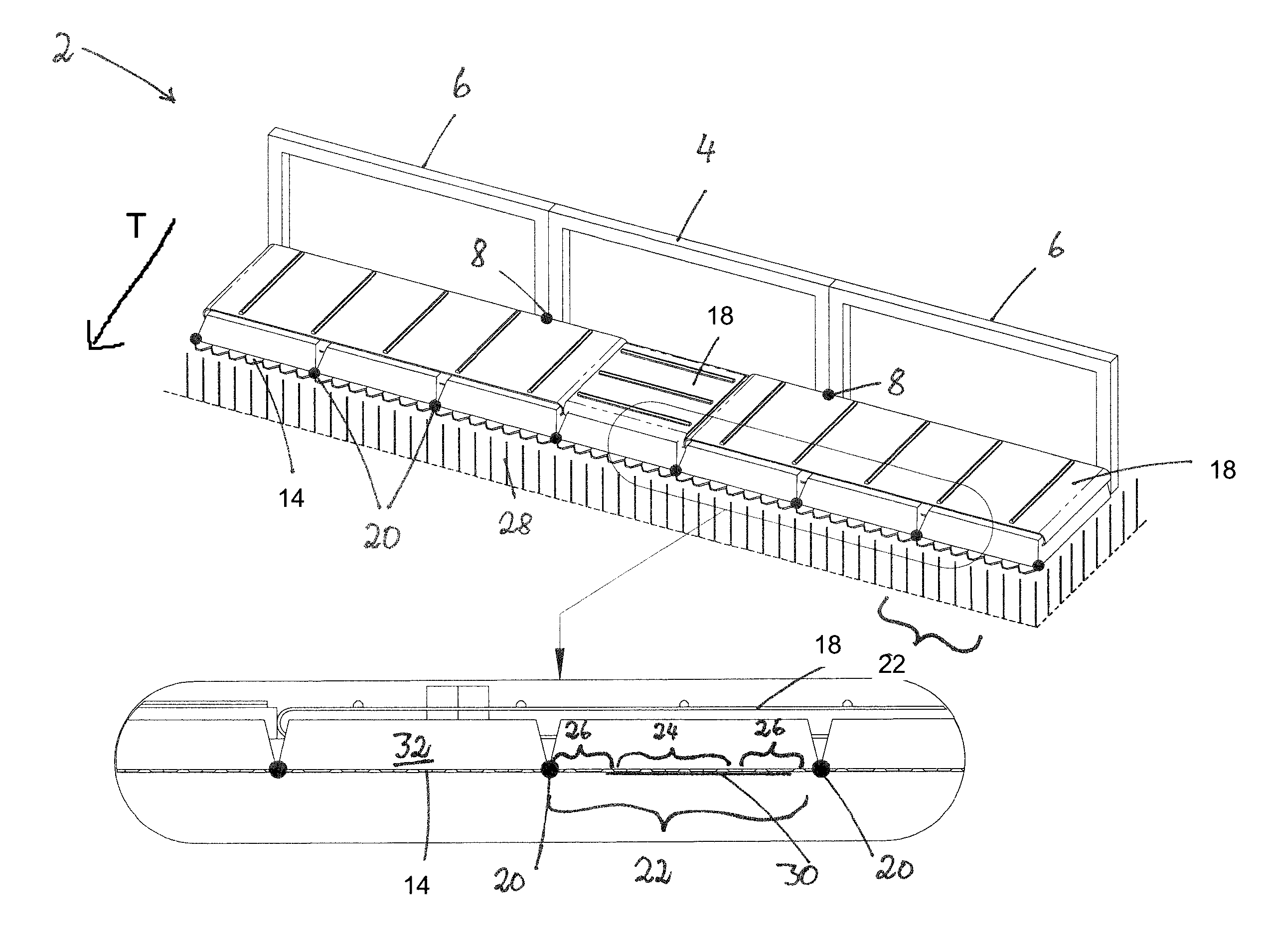
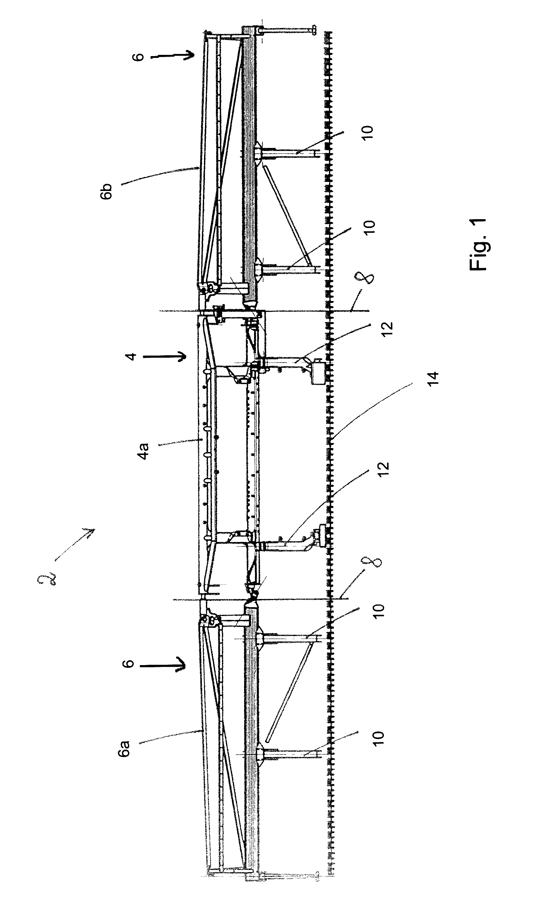
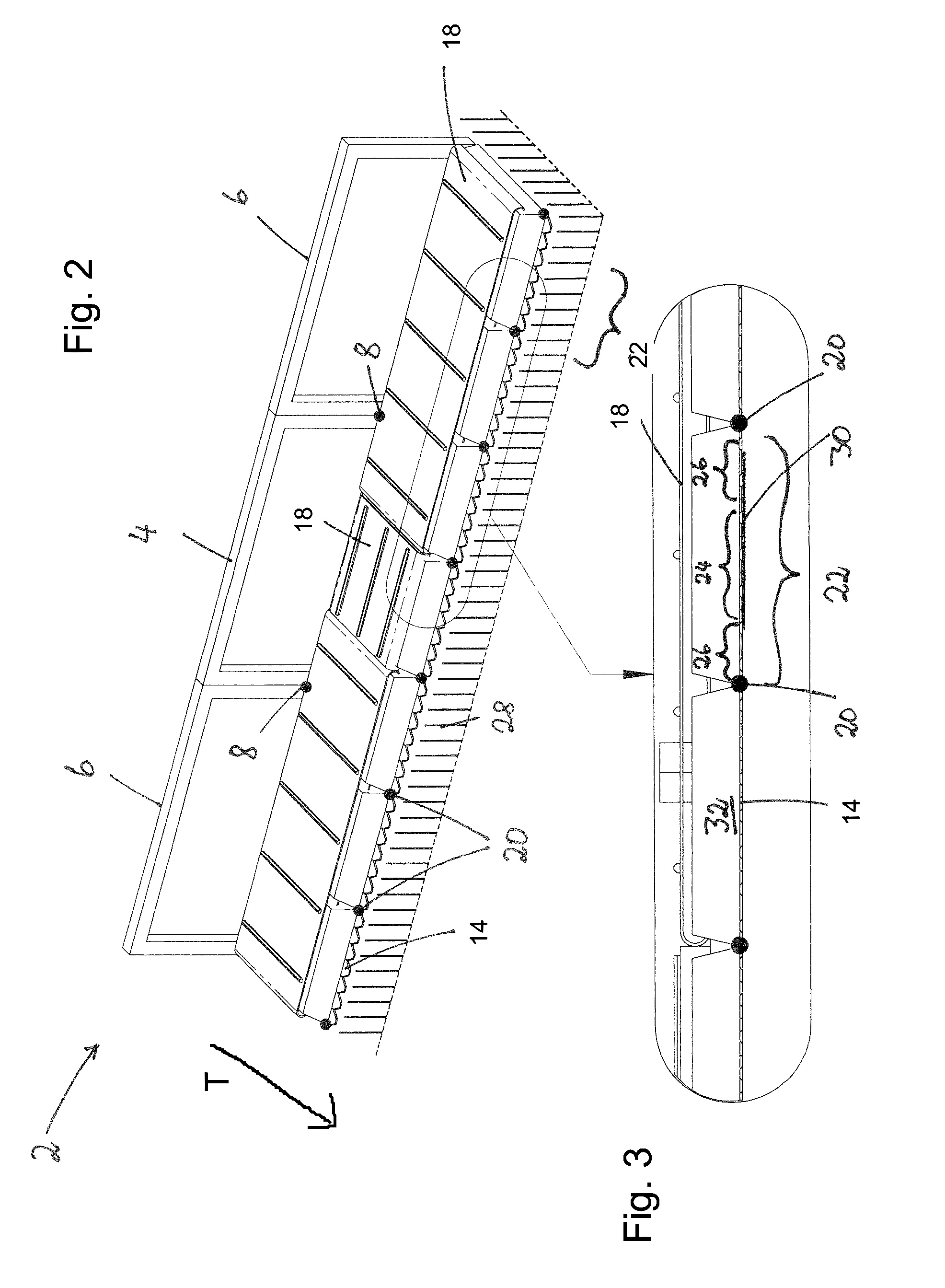
[0019]In the attached drawing, the basic configuration of a draper platform 2 is illustrated. The draper platform 2 comprises a center section 4 and two lateral sections 6 adjoining it laterally. By means of the central section 4, the draper platform 2 can be connected to a harvesting machine, for example, the feed channel of a combine harvester not illustrated in more detail in the drawing. The center section 4 comprises a center frame 4a and the lateral sections 6 each comprise a lateral frame 6a, 6b wherein the lateral frames 6a, 6b of the lateral sections 6 are connected to opposite ends of the center frame 4a of the center section 4 so as to be pivotable about a pivot axis 8, respectively. The pivot axis 8 may be aligned precisely with the forward travel direction of the draper platform 2 but it can also deviate from the forward travel direction T by a few degrees.

[0020]For reasons of simplification, the conveying devices 18 that the draper platform 2 is provided with in the co...


PUM


Abstract

A draper platform for a combine harvester has a center section attachable to a feed channel of the combine harvester. Lateral sections are arranged laterally on opposite ends of the center section. The center section has a center frame; the lateral sections have a lateral frame and are pivotable relative to the center section about a pivot axis that is oriented in travel direction of the draper platform. A cutter bar is provided and pivotable arms having a first end connected to the cutter bar and a second end connected to the center frame or the lateral frames connect the cutter bar pivotably to the center section and the lateral sections. Drive devices are operatively connected to the cutter bar and conveying devices that convey cut stalk material. The pivotable arms are arranged such that less than one of them is present per meter of working width of the draper platform.

Description

BACKGROUND OF THE INVENTION[0001]The present invention relates to a draper platform for attachment to a combine harvester and comprising: a center section that is attachable to the feed channel of a combine harvester and lateral sections arranged laterally thereto, wherein the lateral sections are pivotable about a pivot axis that is oriented at least approximately in travel direction; a cutter bar that is supported by several arms pivotably connected to a frame of the center section or of a lateral section; conveying devices for conveying the cut stalk material; and drive devices for driving the cutter bar and the conveying devices.[0002]U.S. Pat. No. 7,992,372 discloses a draper platform of the aforementioned kind. In addition to the rigid knife holders on the exterior sides, there are also eight pivotably supported arms each on the lateral sections that secure the cutter bar and six pivotably supported arms are mounted on the center section that secure the cutter bar. Across the ...

Claims


Application Information

Patent Timeline
Patent Type & Authority Patents(United States)
IPC IPC(8): A01D43/00A01D61/00A01D41/14A01D61/02A01D41/12
CPCA01D61/002A01D41/12A01D41/144A01D61/02
Inventor SCHULZE SELTING, STEPHANWEBERMANN, DIRKSCHULZE RUCKAMP, JAN BERNDSUDHUES, STEFFENPOKRIEFKE, MICHAEL
Owner CARL GERINGHOFF GMBH & CO KG
Why Eureka
Try Eureka