Electronic cigarette atomizer

a cigarette atomizer and electronic technology, applied in the field of electronic cigarettes, can solve the problems of low production efficiency, difficult to accurately align and assemble the two, and serious inconvenient assembly methods

Inactive Publication Date: 2017-01-03
HUIZHOU KIMREE TECH
View PDF7 Cites 37 Cited by
  • Summary
  • Abstract
  • Description
  • Claims
  • Application Information

AI Technical Summary

Benefits of technology

[0015]When implementing the electronic cigarette atomizer of the present invention, the following advantageous effects can be achieved: the heating wire component and the electrode part are formed integrally, and the assembly of the electronic cigarette atomizer can be accomplished via only the operation of aligning the U-shaped opening(s) with the heating wire component and inserting the U-shaped opening(s) into the heating wire component, and it is unnecessary to perform actions of insertion of the lead pins. An electronic cigarette atomizer in the present invention is simple in assembly, inaccurate alignments formed between the heating wire component and the electrode is avoided, and the production efficiency is improved.
can be achieved: the heating wire component and the electrode part are formed integrally, and the assembly of the electronic cigarette atomizer can be accomplished via only the operation of aligning the U-shaped opening(s) with the heating wire component and inserting the U-shaped opening(s) into the heating wire component, and it is unnecessary to perform actions of insertion of the lead pins. An electronic cigarette atomizer in the present invention is simple in assembly, inaccurate alignments formed between the heating wire component and the electrode is avoided, and the production efficiency is improved.

Problems solved by technology

However, the assembly method is seriously inconvenient.
Furthermore, the lead pins of the heating wire component 140 are very long and may be bent during assembly, and it is difficult to accurately align and assemble the two lead pins of the heating component, which causes low production efficiency.

Method used


Image

  • Electronic cigarette atomizer
  • Electronic cigarette atomizer
  • Electronic cigarette atomizer

Examples


Embodiment Construction

[0022]Specific implementations of the present invention is explained in detail in accordance with accompanying drawings so that the technical feature, objective and effect of the present invention can be understood more clearly.

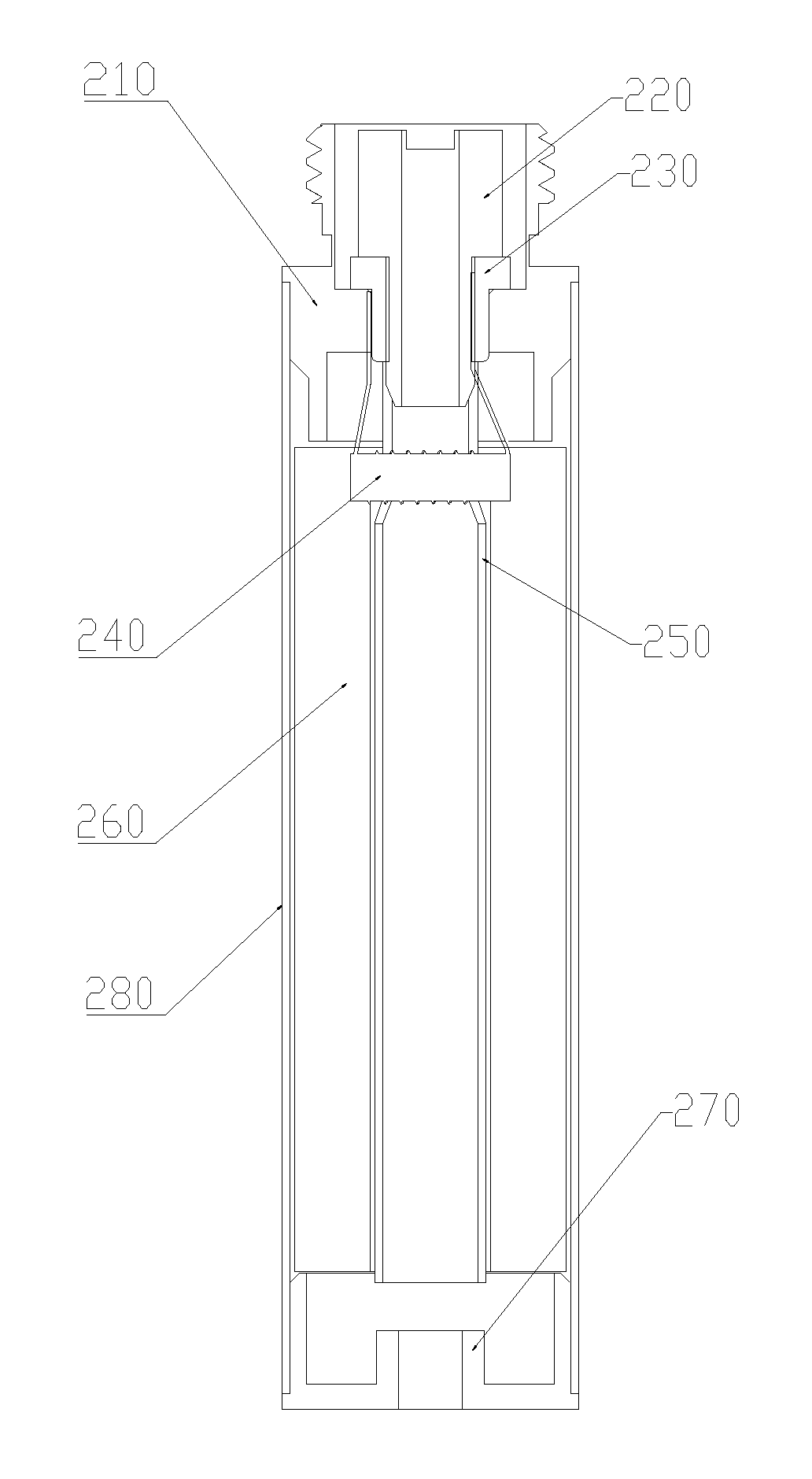
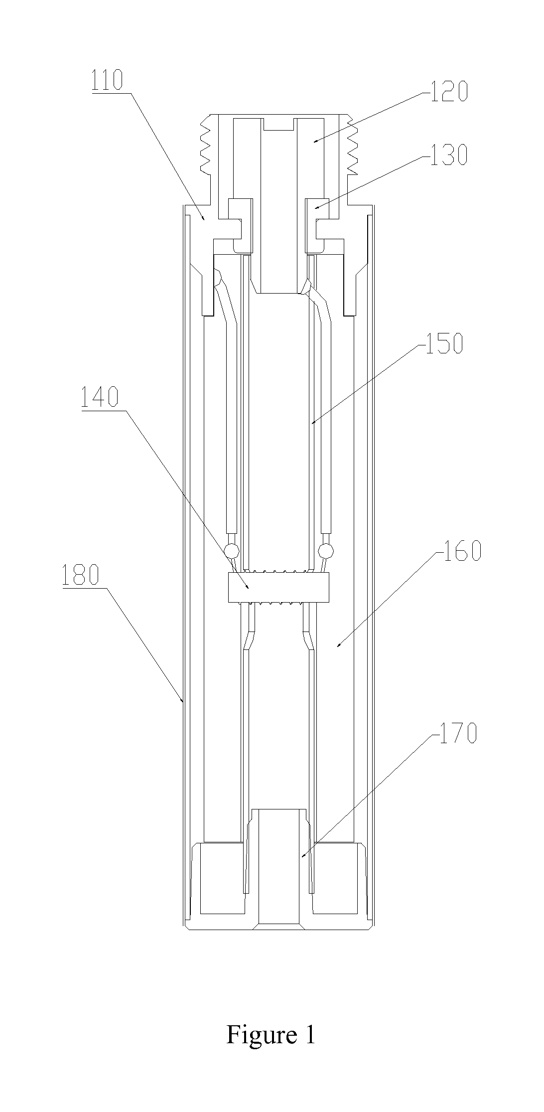
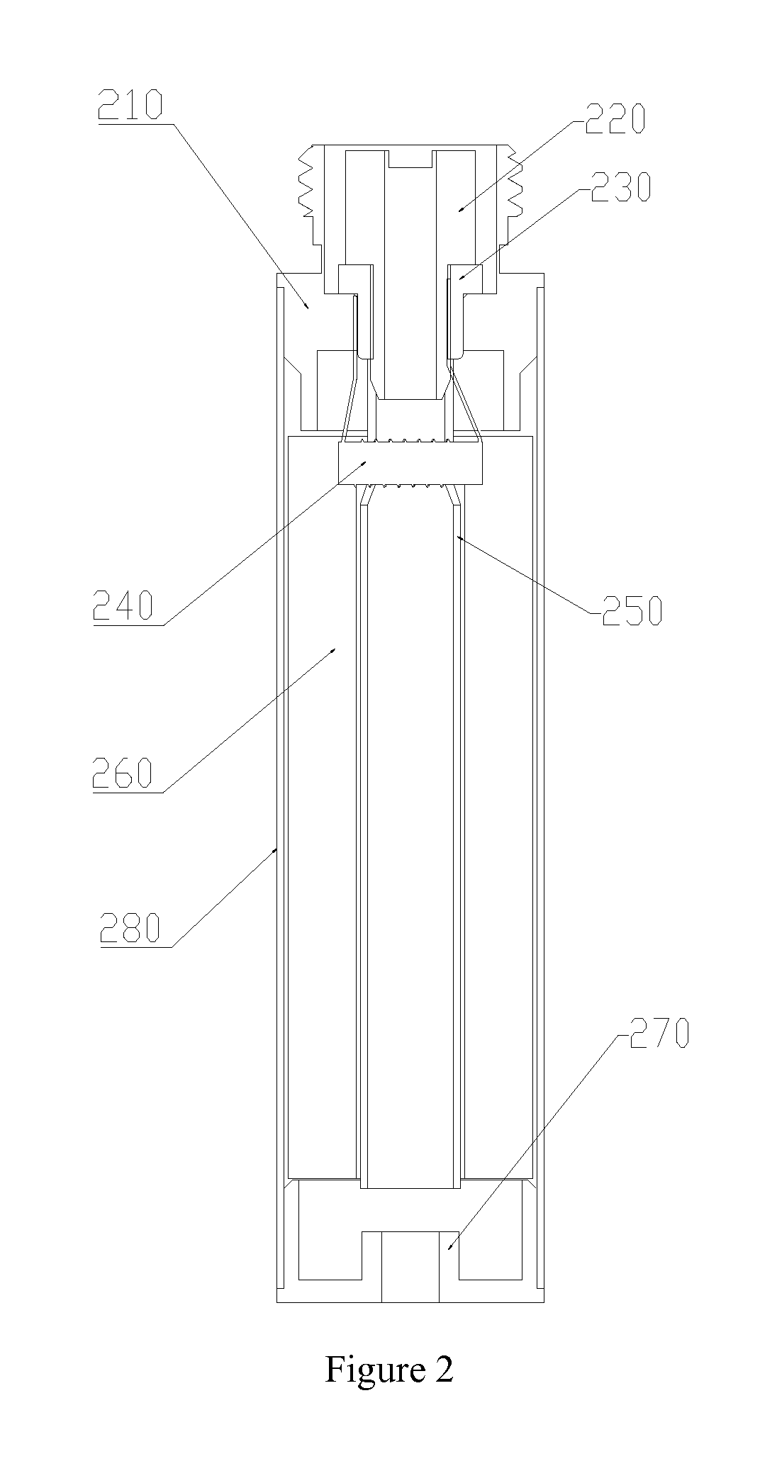
[0023]In order to solve the drawback of low production efficiency caused by the difficulty in assembly of the existing electronic cigarette atomizer shown in FIG. 1, an electronic cigarette atomizer shown in FIG. 2 is provided in the present invention. The electronic cigarette atomizer of the present invention comprises a male screw bushing 210 and a top electrode 220, and the male screw bushing 210 and a battery rod component of an electronic cigarette are assembled together via a threaded connection. When the male screw bushing 210 is connected to the battery rod component, the male screw bushing 210 and the top electrode 220 are connected to a positive electrode and a negative electrode of the battery respectively. To prevent short circuit incidents, the t...


PUM


Abstract

The present invention refers to an electronic cigarette atomizer, which comprises a heating wire component and a breather pipe, the heating wire component further comprises a heating body, one end of the breather pipe defines at least one U-shaped opening(s), the heating body is embedded in the U-shaped opening(s). In assembly of an electronic cigarette atomizer in the present invention, the heating wire component and the electrode part are formed integrally, the assembly of the electronic cigarette atomizer can be accomplished via the operation of aligning the U-shaped opening with the heating wire component and inserting the U-shaped opening into the heating wire component, there is no need to perform actions of insertion of the lead pins. The electronic cigarette atomizer is simple in assembly, the electronic cigarette atomizer avoids inaccurate alignments formed between the heating wire component and the electrode and improves the production efficiency.

Description

CROSS-REFERENCE TO RELATED APPLICATIONS[0001]This application is a continuation of International Patent Application No. PCT / CN2013 / 074371, with an international filing date of Apr. 18, 2013, designating the United States. The contents of these specifications are incorporated herein by reference.FIELD OF THE INVENTION[0002]The present invention relates to the technical field of electronic cigarette, and more particularly, to a kind of electronic cigarette atomizer.BACKGROUND OF THE INVENTION[0003]Electronic cigarette is a kind of electronic products, which is configured for heating tobacco juice by a heating wire and making the tobacco juice be atomized. Nowadays, electronic cigarette are provided to smokers as substitutes of real cigarettes. In use of an electronic cigarette, the tobacco juice is transformed into aerial fog after being heated, and the aerial fog flows through a breather pipe and arrives at the exterior of the electronic cigarette via an opening of a suction nozzle c...

Claims


Application Information

Patent Timeline
Patent Type & Authority Patents(United States)
IPC IPC(8): A24F47/00A24F40/10A24F40/46
CPCA24F47/008A24F40/46A24F40/10
Inventor LIU, QIUMING
Owner HUIZHOU KIMREE TECH
Why Eureka
Try Eureka