Occupant protection device

a technology for occupant protection and head airbags, which is applied in the direction of belt retractors, vehicle components, vehicle arrangements, etc., can solve the problems of limiting the height of the vehicle seat, affecting the deployment performance of the airbag, and the joint strength of the head airbag is difficult to secure, so as to facilitate inflation and deployment

Active Publication Date: 2017-01-03
TOYOTA JIDOSHA KK
View PDF21 Cites 47 Cited by
  • Summary
  • Abstract
  • Description
  • Claims
  • Application Information

AI Technical Summary

Benefits of technology

[0023]In the fifth aspect, a gap between the headrest and the ceiling section is widened by lowering the vehicle seat to the lowermost step position. In this state, the headrest is moved in the seat upward direction, after which the airbag housed in the headrest is inflated and deployed, thereby enabling the airbag to be suppressed from impinging on the head of the occupant during the inflation and deployment process. Further, moving the headrest in the seat upward direction enables the airbag to be deployed from a high position. Accordingly, there is no need to deploy the airbag in the seat upward direction, thereby enabling the airbag to be suppressed from strongly impinging on the ceiling section.
[0024]The fifth aspect facilitates inflation and deployment of the airbag so as to pass above the head of the occupant.

Problems solved by technology

In the configuration of JP-A No. 2000-344044, the gas supply pipe extends out further to a vehicle upper side than a headrest, resulting in a narrow gap to a ceiling section of the vehicle, thus limiting the height of the vehicle seat.
In the configuration of JP-A No. 2103-018378, it is difficult to secure the joint strength of the pair of head airbags that join up after inflating and deploying, and the joint strength of the auxiliary head airbag to the pair of head airbags.
However, since it is necessary to inflate and deploy the airbag so as to pass above the head of the occupant, if a gap between the headrest and the ceiling section is narrow, the airbag might strongly impinge on the ceiling section, affecting the deployment performance of the airbag.

Method used


Image

  • Occupant protection device
  • Occupant protection device
  • Occupant protection device

Examples


Embodiment Construction

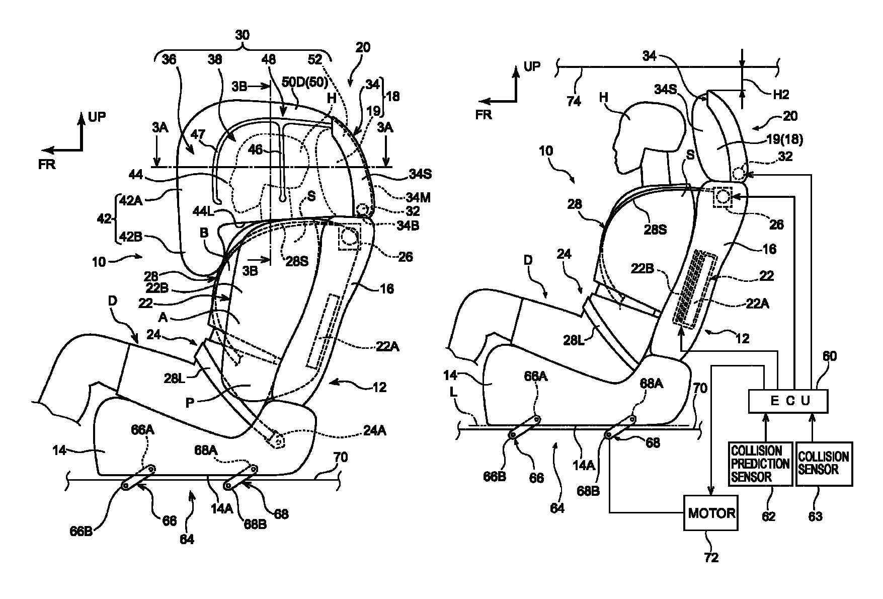
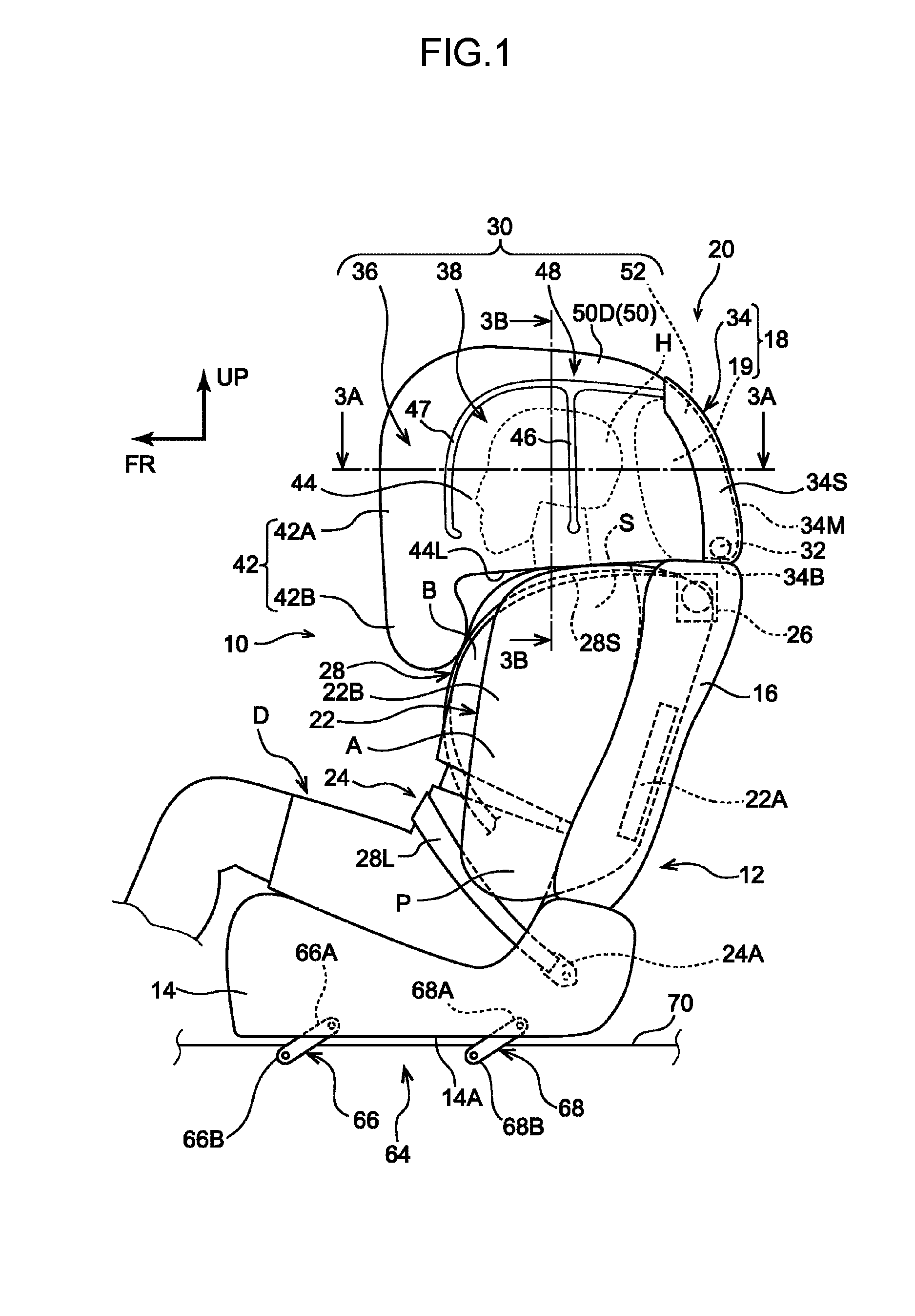
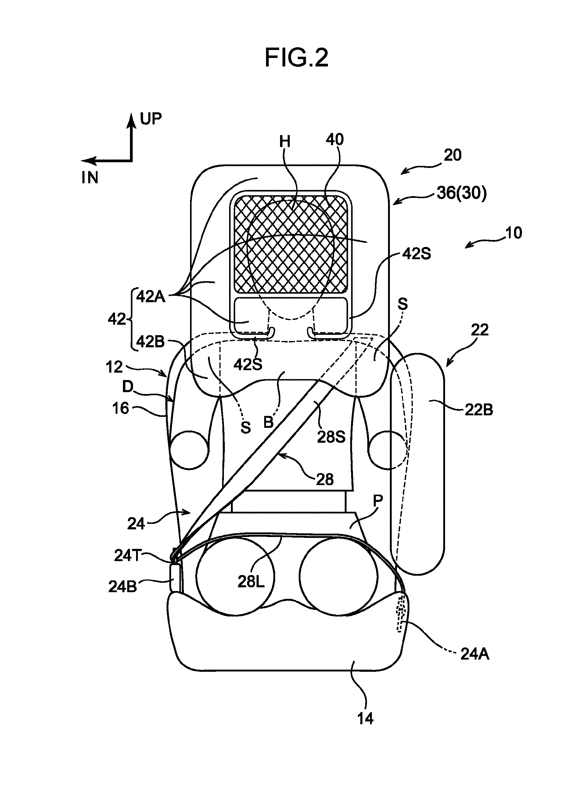
[0033]Explanation follows regarding an occupant protection device 10 according to an exemplary embodiment of the present disclosure, with reference to FIG. 1 to FIG. 5. Note that in the drawings, the arrow FR and the arrow UP respectively indicate a front direction (the direction in which a seated occupant faces) and an upward direction of a vehicle seat 12 as appropriate. In the following explanation, unless specifically indicated, reference simply to the front and rear, up and down, and left and right directions indicates the front and rear in a seat front-rear direction, up and down in a seat vertical direction, and left and right as facing forward in the seat front-rear direction. In the drawings, the arrow IN indicates a vehicle width direction central side as appropriate in an automobile, serving as a vehicle, installed with the vehicle seat 12.

[0034]Schematic Overall Configuration of Occupant Protection Device

[0035]As illustrated in FIG. 1 and FIG. 2, the occupant protection ...


PUM


Abstract

An occupant protection device is provided including (1) an airbag that covers the head of the occupant, and that has (i) a front deployment section that is housed in a headrest, and that is deployed at a seat forward direction with respect to the head of a seated occupant, and (ii) a pair of left and right lateral deployment sections that are inflated and deployed at seat sides with respect to the head of the seated occupant, (2) a lifting mechanism that raises and lowers the vehicle seat, and (3) a controller that uses the lifting mechanism to lower the vehicle seat to an airbag deployable height in cases in which a vehicle collision has been determined to be unavoidable and a height of the vehicle seat is higher than the airbag deployable height, and that inflates and deploys the airbag after lowering the vehicle seat.

Description

CROSS-REFERENCE TO RELATED APPLICATION[0001]This application claims priority under 35 USC 119 from Japanese Patent application No. 2015-139494 filed on Jul. 13, 2015, the disclosure of which is incorporated by reference herein.BACKGROUND[0002]Technical Field[0003]The present disclosure relates to an occupant protection device.[0004]Related Art[0005]Airbag devices are known in which gas from an inflator is supplied through a gas supply pipe fixed to a seatback to a bag attached to the gas supply pipe, and the bag is inflated so as to cover an occupant from the front and the side (see Japanese Patent Application Laid-Open (JP-A) No. 2000-344044). Airbag devices are also known in which head airbags protrude out from left and right end portions of a seat headrest toward the front, and join up in front of the head of an occupant, and an auxiliary head airbag protrudes out from a central portion of the headrest and joins up with the pair of head airbags (see JP-A No. 2013-018378).[0006]In...

Claims


Application Information

Patent Timeline
Patent Type & Authority Patents(United States)
IPC IPC(8): B60R21/207B60R21/233B60R22/46B60R21/0134B60N2/427B60R21/231B60R21/02B60R21/00
CPCB60R21/23138B60R21/207B60R21/0134B60N2/42736B60N2/4279B60R22/46B60R21/233B60N2/427B60R2021/0048B60R2021/2074B60R2021/0032B60R2021/23146B60R2021/0273B60R2021/23308B60R2021/23107B60R2021/01252B60R2021/01034B60R2021/23115B60R2021/01211B60R2021/01272B60R21/231B60N2/688B60N2/914
Inventor OHNO, MITSUYOSHIISHIDA, SHINICHI
Owner TOYOTA JIDOSHA KK
Why Eureka
Try Eureka