Impact tool

a tool and impact technology, applied in the field of impact tools, can solve the problems of not providing a not durable, and achieve the effect of high repeatability and consistent level of impact for

Inactive Publication Date: 2017-01-17
BOICE MARK
View PDF31 Cites 7 Cited by
  • Summary
  • Abstract
  • Description
  • Claims
  • Application Information

AI Technical Summary

Benefits of technology

[0007]The impact tool provides a consistent level of impact force for each application or use. This is accomplished by providing for certain key features within the internal mechanism of the impact tool which may include but is not limited to any one or more of the following features. For example, a slug within the impact tool has a conical distal surface which engages a proximal end of a trip release member. The conical distal surface provides a linear resistance to the trip release member as the trip release member lines up to the center of the slug. The linear resistance provides the consistent repeatable level of impact for each use. Moreover, when the slug is forcibly pushed forward toward the contact surface areas of the trip release member and the hammer, the trip release member contacts the hammer in the same area for each cycle leading to a highly repeatable and consistent level of impact force. The area of contact between the trip release member and the hammer is the same for each repeated use thereby providing a consistent level of impact force for each use. In particular, the distal end of the release member has a spherical configuration which matches a spherical configuration of a proximal end of the hammer. Also, a diameter of the distal end of the trip release member is smaller than the proximal end of the hammer so that the entire surface of the distal end of the trip release member always contacts the hammer when the slug pushes forward to create the impact force. The impact tool also provides for use of an asymmetrical head by locking rotation of the hammer so that the asymmetrical head which applies the impact force to the surface does not rotate before and after impact. Moreover, the trip release member is biased to a tilted configuration by a conical compression spring that is skewed about its length.

Problems solved by technology

However, these center punches suffer in that they do not provide a consistent level of impact force at the same setting and also are not durable over an extended period of use.

Method used


Image

  • Impact tool
  • Impact tool
  • Impact tool

Examples


Embodiment Construction

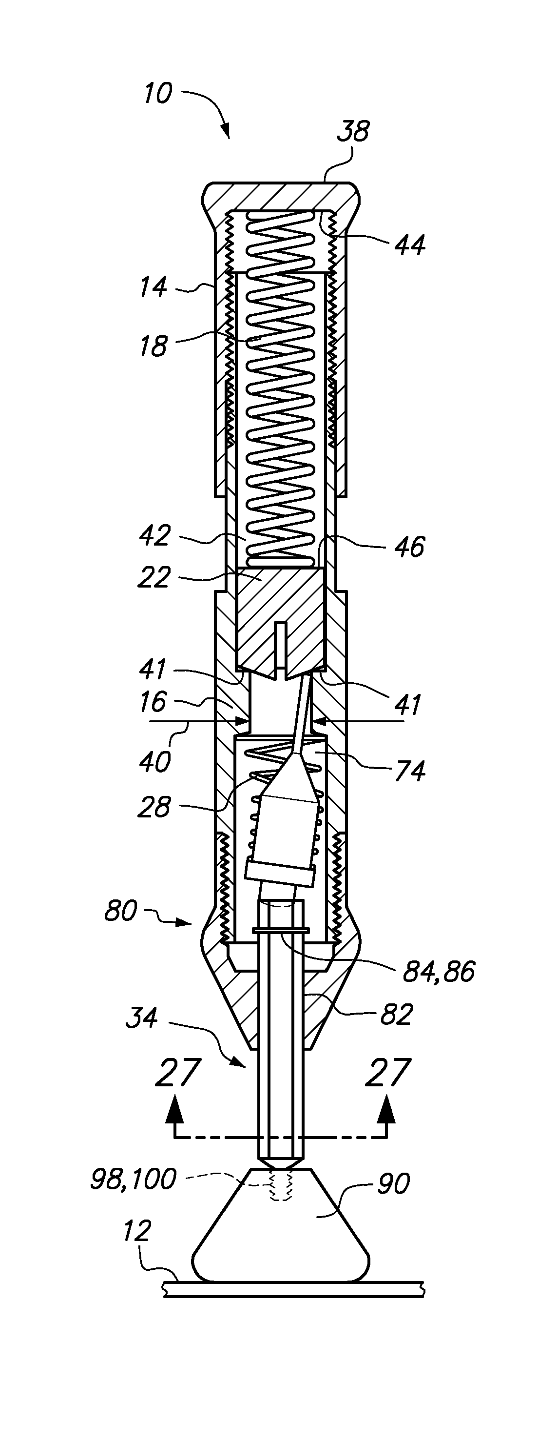
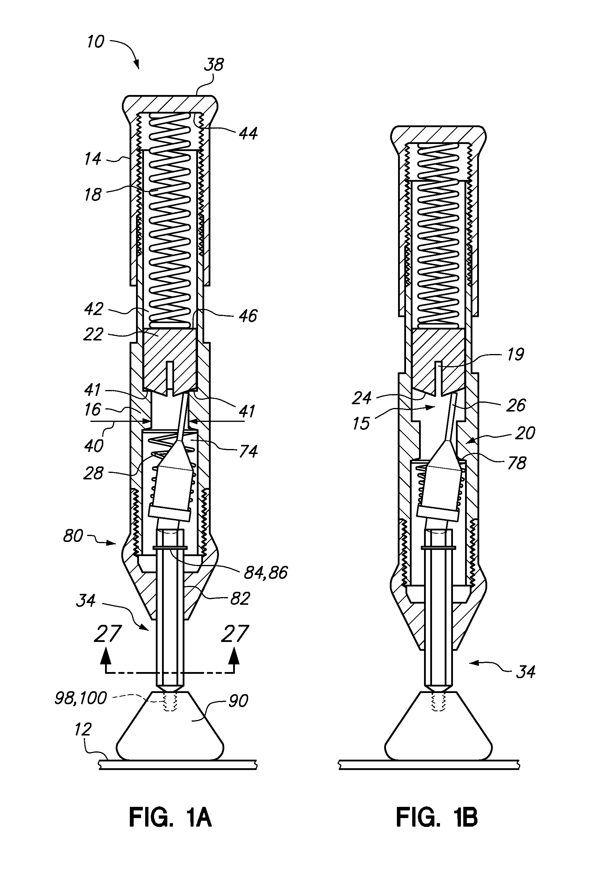
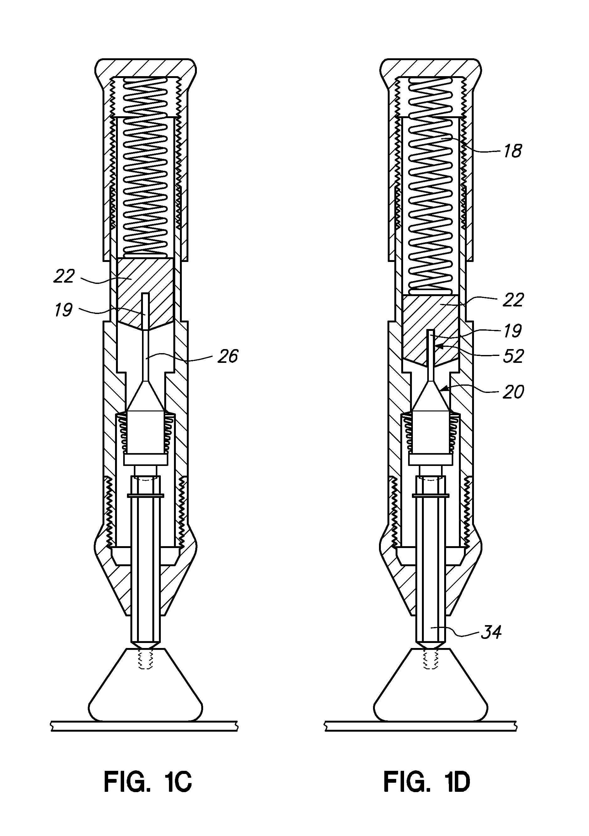
[0048]Referring now to the drawings, an impact tool 10 is shown which can provide a variable measured impact force to a surface 12 by adjusting a cover 14 up or down on a body 16 of the impact tool 10. The cover 14 when adjusted down on the body 16 increases a preload of a spring 18 while adjusting the cover 14 upward on the body 16 decreases the preload of the spring 18. The user pushes the impact tool 10 on the surface 12 further compressing the spring until a trip release member 20 is aligned to a central aperture 19 of a slug 22 (see FIG. 1C). When the trip release member is aligned to the central aperture 19, the slug 22 is forcibly pushed into the trip release member 20 (see FIG. 1D) to create the measured impact force. In order to provide a consistent measured impact force, a distal end of the slug 22 has a conical surface 24 to help smoothly guide a proximal end 26 of the trip release member 20 on the conical surface 24 into the central aperture 19 of the trip release member...


PUM

PropertyMeasurementUnit
angleaaaaaaaaaa
angleaaaaaaaaaa
angleaaaaaaaaaa

Abstract

An impact tool which provides a consistent level of impact force is provided. The internal mechanism of the impact tool has a trip release member and a hammer which remains in constant contact over a constant surface area throughout cycling of the impact tool. Additionally, the trip release member may slide against a slug having a straight conical surface to minimize variation. Moreover, the hammer may be non-rotateable so that a non round or asymmetrical head may be used.

Description

CROSS-REFERENCE TO RELATED APPLICATIONS[0001]This application claims the benefit of provisional patent application Ser. No. 61 / 688,633, filed on May 18, 2012, the entire contents of which is expressly incorporated herein by reference.STATEMENT RE: FEDERALLY SPONSORED RESEARCH / DEVELOPMENT[0002]Not ApplicableBACKGROUND[0003]The various embodiments disclosed herein relate to an impact tool for providing a measured impact forced to a surface, and more particularly for providing a new use for a center punch.[0004]Various center punches exist in the prior art. The center punches provide an impact force to a local area on a surface. However, these center punches suffer in that they do not provide a consistent level of impact force at the same setting and also are not durable over an extended period of use.[0005]Accordingly, there is a need in the art for an improved center punch and also for extending the use of center punches.BRIEF SUMMARY[0006]The various aspects of the impact tool descr...

Claims


Application Information

Patent Timeline
Patent Type & Authority Patents(United States)
IPC IPC(8): B25D5/02B25B19/00
CPCB25D5/02B25D2250/371B25D2250/005
Inventor BOICE, MARK
Owner BOICE MARK
Why Eureka
Try Eureka