Jet propelled watercraft

a technology for watercraft and jets, applied in marine propulsion, special-purpose vessels, vessel construction, etc., can solve problems such as inability to reach the connecting port, and achieve the effect of improving the stability of the air intake box with respect to the engin

Active Publication Date: 2017-01-17
YAMAHA MOTOR CO LTD
View PDF3 Cites 0 Cited by
  • Summary
  • Abstract
  • Description
  • Claims
  • Application Information

AI Technical Summary

Benefits of technology

[0011]As a result, when water flows into the interior of the air intake box, entry thereof into the engine is prevented.
[0033]According to this arrangement, by turning and mounting the air intake box on the engine, the intake pipe extending from the air intake box is also connected to the engine. Thus, the stability of the air intake box with respect to the engine is further improved.

Problems solved by technology

Thus, even when water flows into the internal space from the inlet, because the water has difficulty in rising from the lower region to the upper region due to its own weight, it thus cannot reach the connecting port.

Method used


Image

  • Jet propelled watercraft
  • Jet propelled watercraft
  • Jet propelled watercraft

Examples


Embodiment Construction

[0056]Hereinafter, preferred embodiments of the present invention will be described in detail with reference to the accompanying drawings.

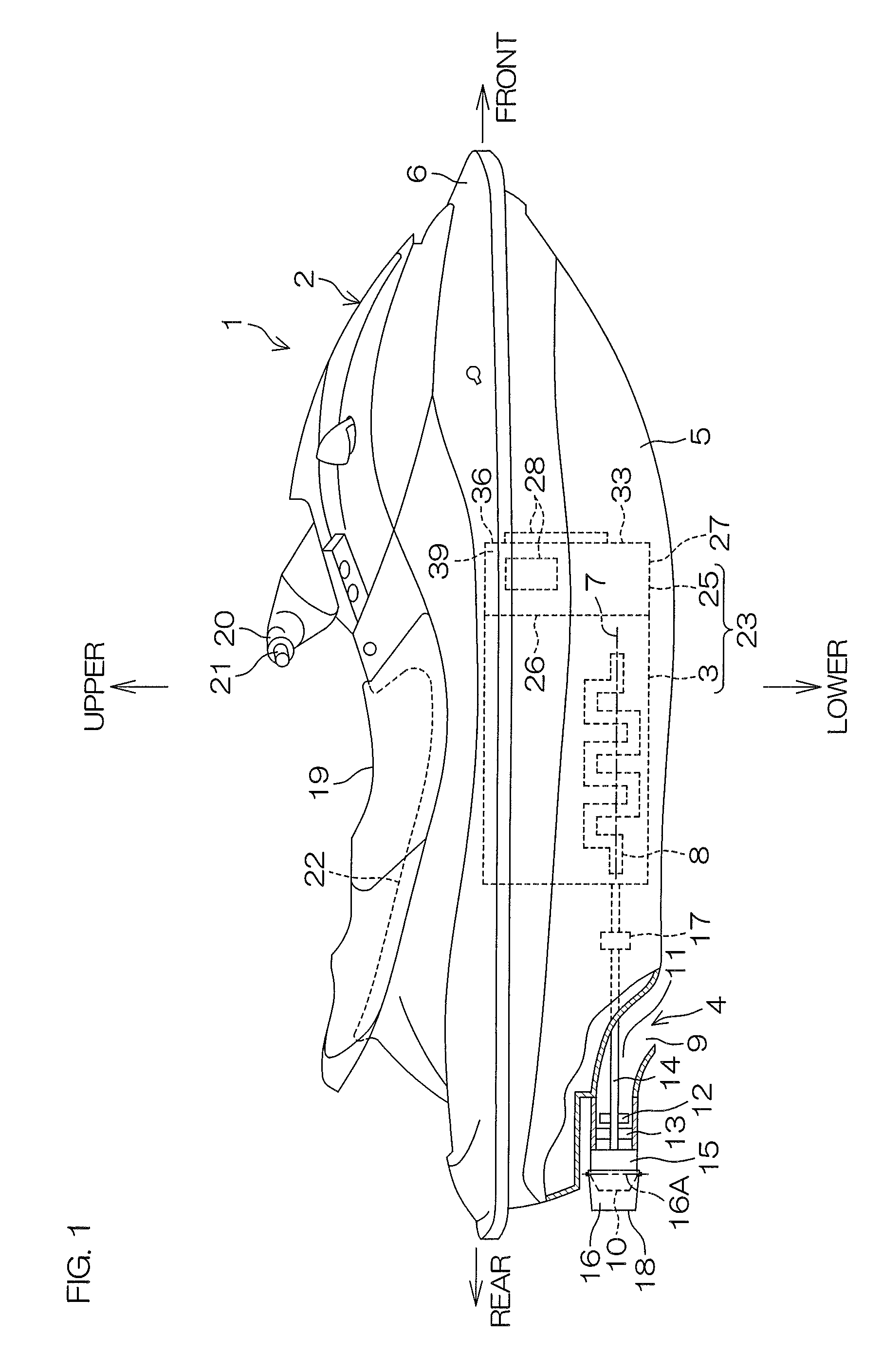
[0057]FIG. 1 is a schematic view of a jet propelled watercraft 1 according to a preferred embodiment of the present invention. A right-left direction in FIG. 1 is defined as the front-rear direction of the jet propelled watercraft 1, the right side in FIG. 1 is defined as the front of the jet propelled watercraft 1, and the right-left direction of the jet propelled watercraft 1 faces the traveling direction of the jet propelled watercraft 1. Thus, the near side in a direction perpendicular to the sheet of FIG. 1 corresponds to the right side of the jet propelled watercraft 1, and the far side in a direction perpendicular to the sheet of FIG. 1 corresponds to the left side of the jet propelled watercraft 1.

[0058]As shown in FIG. 1, the jet propelled watercraft 1 includes a watercraft body 2, an engine 3 accommodated in an interior of the watercraft...


PUM


Abstract

A jet propelled watercraft includes a watercraft body, an engine in the watercraft body, a jet pump configured to generate a jet thrust by a driving force of the engine, an intake pipe configured to supply air to the engine, an air intake box, and a filter. The air intake box includes a connecting port connected to the intake pipe and an inlet configured to take in ambient air. The filter is disposed in a space in an internal space of the air intake box. The filter divides the space into a lower region and an upper region. The lower region is connected to the inlet and the upper region is located higher than the lower region and connected to the connecting port. The filter is configured to clean air taken into the internal space from the inlet and directed to the connecting port.

Description

BACKGROUND OF THE INVENTION[0001]1. Field of the Invention[0002]The present invention relates to a jet propelled watercraft.[0003]2. Description of the Related Art[0004]A small vessel disclosed in Japanese Patent Application Publication No. 2002-114192 is provided with an internal combustion engine and an intake device configured to supply air to the internal combustion engine in the body. The intake device includes an intake pipe extending upward from a cylinder of the internal combustion engine, an intake chamber covering an upper end of the intake pipe, and an air filter provided continuously from the intake chamber. The air filter includes a filter case having an internal space communicating with an interior of the intake chamber in a horizontal direction and an element unit accommodated in an interior of the filter case for cleaning air.[0005]The element unit includes an element having an annular shape in a plan view and an upper plate and lower plate that sandwich the element ...

Claims


Application Information

Patent Timeline
Patent Type & Authority Patents(United States)
IPC IPC(8): B63H11/04B63B35/73B63H21/30F02M35/16
CPCB63H11/04B63B35/731B63H21/305F02M35/168B63B34/10
Inventor TERADA, KOHEIMIURA, HIRONOBU
Owner YAMAHA MOTOR CO LTD
Why Eureka
Try Eureka