
Flaring and swaging bits, and methods using same

a technology of metal fabrication tools and swaging bits, which is applied in the field of metal fabrication tools, can solve the problems of laborious and imprecise fitting process, and achieve the effect of increasing the diameter of at least a portion of the tube and increasing the structural quality of the tub

Active Publication Date: 2017-01-24
DIVERSITECH
View PDF1 Cites 2 Cited by
  • Summary
  • Abstract
  • Description
  • Claims
  • Application Information

AI Technical Summary

Benefits of technology

[0004]Disclosed subject matter provides flaring and swaging tools that avoid or reduce risk of cracking in the wall of tube being fitted. In an embodiment, flaring and swaging tools do not create flares or swages at room temperature, and thus do not harden the flared material to an undesirable degree, in this manner do not increase the risk of cracking the wall of the tube.
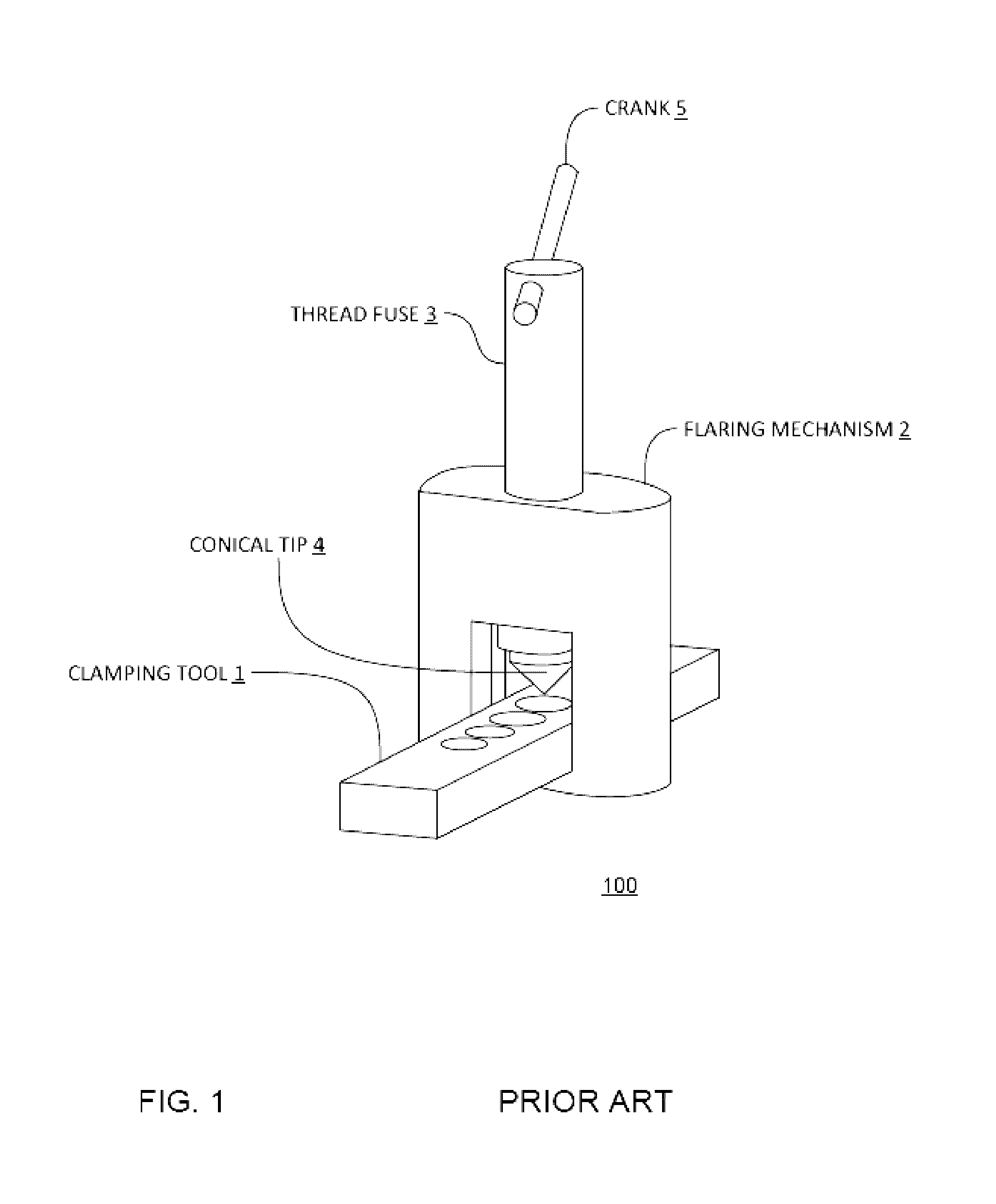
[0005]Disclosed subject matter eliminates the need for using an extra clamping tool when flaring and swaging, and eliminates the labor and time for a technician to couple the tube into a clamping tool. Disclosed subject matter eliminates the performing of flaring and swaging at room temperature, and thus avoids contributing to undesirable brittleness and susceptibility or risk of the wall cracking during fitting or thereafter, such as during expansion of the tube. In an embodiment, swaging and flaring tools require reduced or minimal spaced compared to previous tools, and methods for swaging and flaring with tools as disclosed may be performed during tube installation by a technician in less space than for previous tools and methods.
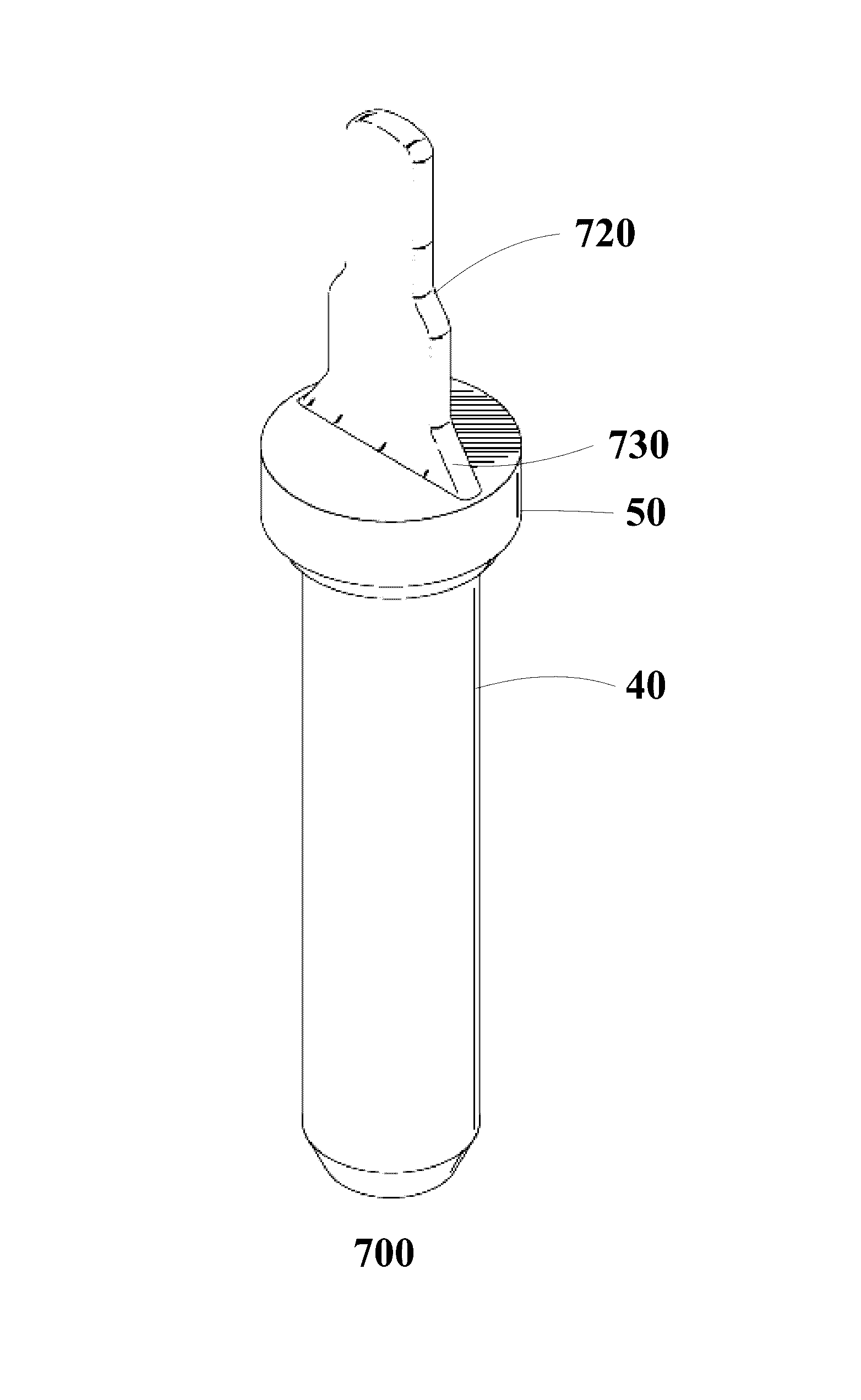
[0009]In an embodiment, a method may further comprise inserting the rotary insert into an interior surface of a tube to cause friction between the tip and an interior surface of the tube, to increase the diameter of at least a portion of the tube, to create a flare, and to increase structural quality of the tube from heat provided to the tube.
[0011]A method may further comprise inserting the rotary insert into an interior surface of a tube to cause friction between the tip and an interior surface of the tube, to increase the diameter of at least a portion of the tube, and to increase structural quality of the tube from heat provided to the tube.

Problems solved by technology

Fitting can be a very laborious and imprecise process.

Method used


Image

  • Flaring and swaging bits, and methods using same
  • Flaring and swaging bits, and methods using same
  • Flaring and swaging bits, and methods using same

Examples


Embodiment Construction

[0031]Reference now should be made to the drawings, in which the same reference numbers are used throughout the different figures to designate the same components.

[0032]It will be understood that, although the terms first, second, third, etc. may be used herein to describe various elements, these elements should not be limited by these terms. These terms are only used to distinguish one element from another element. Thus, a first element discussed below could be termed a second element without departing from the teachings of the present disclosure.

[0033]The terminology used herein is for the purpose of describing particular embodiments only and is not intended to be limiting. As used herein, the singular forms “a”, “an”, and “the” are intended to include the plural forms as well, unless the context clearly indicates otherwise. It will be further understood that the terms “comprises” and / or “comprising” or “includes” and / or “including” when used in this specification, specify the pre...


PUM

PropertyMeasurementUnit
angleaaaaaaaaaa
diameteraaaaaaaaaa
angleaaaaaaaaaa

Abstract

Embodiments provide improved flaring and swaging bits, and methods for flaring and swaging.

Description

RELATED APPLICATION[0001]This application is a continuation-in-part of PCT Application Serial No. PCT / BR2013 / 000379 filed 30 Sep. 2013, and pending, which is hereby incorporated by reference in its entirety.FIELD[0002]This disclosure is related to metal fabrication tools, and more specifically is related to flaring and swaging metal fabrication tools, and methods using the same.BACKGROUND[0003]Fitting metal tubes together often requires manual pounding or pressing of the ends of the metal tubes, so as to modify the ends to fit together. Fitting can be a very laborious and imprecise process. A few models of tools in the market are available to perform flares and swages, the majority being concentric flaring and swaging tools and eccentric flaring tools:BRIEF SUMMARY[0004]Disclosed subject matter provides flaring and swaging tools that avoid or reduce risk of cracking in the wall of tube being fitted. In an embodiment, flaring and swaging tools do not create flares or swages at room t...

Claims


Application Information

Patent Timeline
Patent Type & Authority Patents(United States)
IPC IPC(8): B21D39/08B21D41/02B21D19/08
CPCB21D39/08B21D41/021B21D19/08B21D41/02
Inventor ANJOS, BRUNO
Owner DIVERSITECH
Learn More