Dentists' preparation instrument

a technology for dental care and instruments, applied in the field of dental care preparation instruments, can solve problems such as curtain flow breakage, and achieve the effect of preventing flow loss

Active Publication Date: 2017-01-31
SIRONA DENTAL SYSTEMS
View PDF11 Cites 0 Cited by
  • Summary
  • Abstract
  • Description
  • Claims
  • Application Information

AI Technical Summary

Benefits of technology

[0010]To increase the deceleration effect, an eddy chamber which is connected to the discharge port may be provided in the return air duct, the width of this eddy chamber across the longitudinal axis and across the direction of flow of the return air duct amounting to at least 1.2 to 3 times a reference variable a, and its length LW in the direction of flow of the return air duct amounting to at least 0.3 to 1.5 times reference variable a, where the reference variable a is expressed either as a range from 0.5 to 1.5 times the smallest width w or as a range from 0.5 to 1.5 times the height HLA of the blades 11 of the rotor 6.
[0020]The eddy chamber may have rounded discharge edges in the return air duct to prevent flow losses at the typical operating rotational speeds.

Problems solved by technology

During functional operation, however, there is a break in the curtain flow because of the pressure gradient.

Method used


Image

  • Dentists' preparation instrument
  • Dentists' preparation instrument
  • Dentists' preparation instrument

Examples


Embodiment Construction

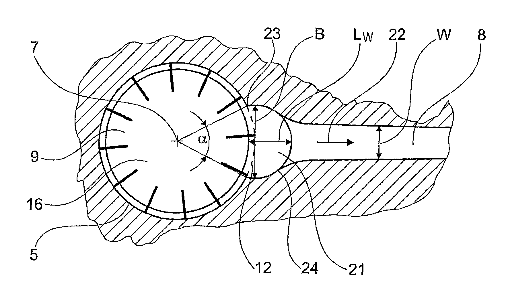
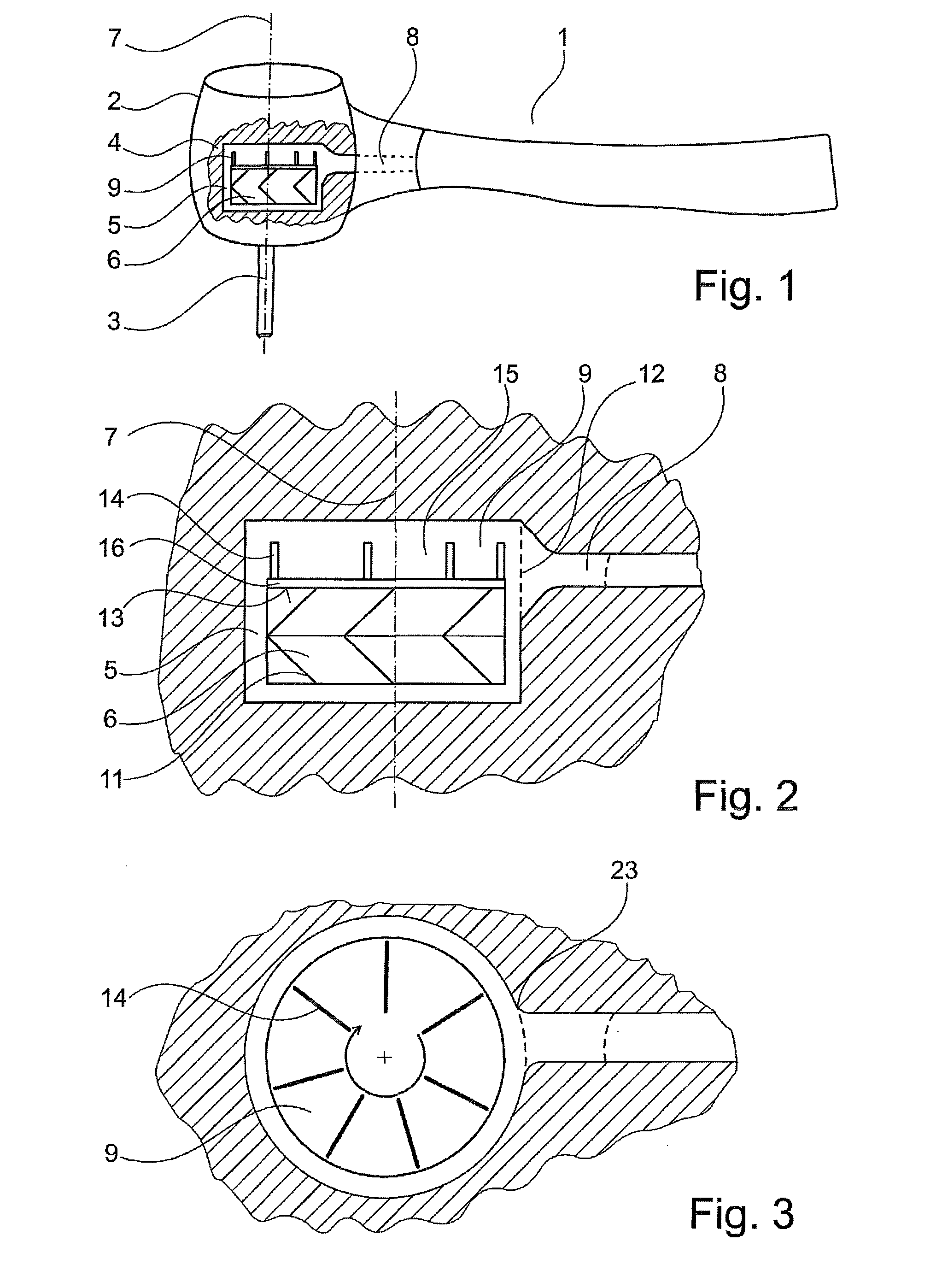
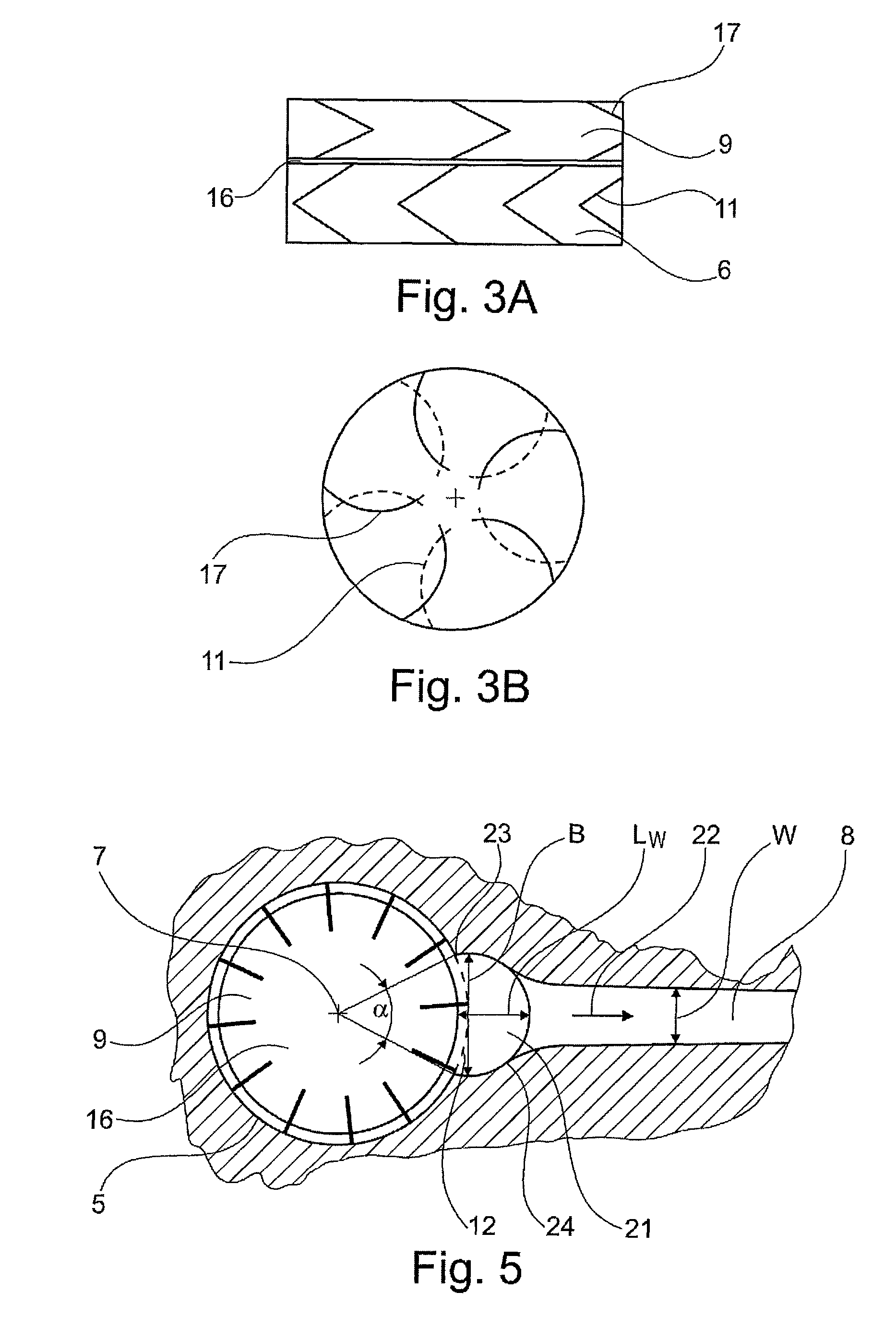
[0029]FIG. 1 shows, schematically in a partially cutaway side view, a dentists' preparation instrument 1, having a turbine 4 that is acted upon by compressed air to drive a driven tool 3 that is mounted in a head part 2. The turbine 4 comprises a turbine compartment 5, in which a rotor 6 is mounted to rotate about a longitudinal axis 7. The bearing of the rotor 6 in the head part 2 itself and the cooperation of the rotor 6 with the tool 3 are not shown here; reference is made in this regard to the prior art, from which a wide variety of approaches are known from the documents cited in the introduction, for example.

[0030]In addition to a compressed air supply (not shown), a return air duct 8, which carries the compressed air out of the turbine compartment 5, is provided in the head part 2, so that compressed air is passed through a handle part to a coupling part of the preparation instrument, as is also known from the prior art.

[0031]FIG. 1 already shows that the rotor 6 is provided ...


PUM


Abstract

A dentists' preparation instrument (1) comprises a turbine (4) for driving a tool (3) using compressed air, and a rotor (6) that is arranged in a turbine compartment (5), rotates about a longitudinal axis (7), and has blades (11) extending to a face (13) of the rotor (6). The turbine compartment (5) has a discharge port (12) for the compressed air towards a returning air duct (8). Said discharge port (12) is disposed in such a way that both the face (13) of the rotor (6) and parts of the blades (11) sweep past the discharge port (12) as the rotor rotates about the longitudinal axis (7). For deceleration purposes, the rotor (6) has a deceleration contour (9) on the face (13), said deceleration contour being formed by projections (14), and the turbine compartment (5) has a deceleration contour chamber (15) inside which the deceleration contour (9) is accommodated. The discharge port (12) in part also extends across the deceleration contour chamber (15).

Description

CROSS-REFERENCE TO RELATED APPLICATIONS[0001]This application is a national stage entry of International Application No. PCT / EP2013 / 065057, filed Jul. 17, 2013, which claims priority to German Patent Appln. No. 10 2012 212 480.2 filed Jul. 17, 2012.BACKGROUND OF THE INVENTION[0002]Field of the Invention[0003]The invention relates to a dentists' preparation instrument having a turbine for driving a tool by means of compressed air. A rotor disposed in a turbine compartment and rotating about a longitudinal axis has blades extending to a face of the rotor. The turbine compartment has a discharge port for the compressed air to a return air duct, wherein the discharge port is disposed in the turbine compartment in such a way that the face of the rotor passes by the discharge port laterally in rotation about the longitudinal axis.[0004]Description of the Related Art[0005]A dental turbine handpiece is known from EP 0 974 308 B1 with which, after the turbine has been shut down, because of t...

Claims


Application Information

Patent Timeline
Patent Type & Authority Patents(United States)
IPC IPC(8): A61C1/05
CPCA61C1/05
Inventor REIN, MATTHIASGOISSER, SIEGFRIEDERTUGRUL, METINSUTTER, RALFMUHLBEYER, ALEXANDER
Owner SIRONA DENTAL SYSTEMS
Why Eureka
Try Eureka