Coolant compressor

Inactive Publication Date: 2020-12-10
NIDEC GLOBAL APPLIANCE GERMANY GMBH
View PDF0 Cites 0 Cited by
  • Summary
  • Abstract
  • Description
  • Claims
  • Application Information

AI Technical Summary

Benefits of technology

[0029]An additional especially preferred embodiment variant of the invention provides that the contact portion is arranged substantially parallel to a bore axis of the suction opening and that the connecting portion has at least one V-shaped bend, wherein a plane formed by the contact element is preferably oriented parallel to the longitudinal axis of the crankshaft. A contact portion of the contact element, at least portions of which are inside the cylinder head arrangement, for example inside the cylinder head cover or inside a suction

Problems solved by technology

A disadvantage of the prior art is that an undefined state arises during the opening movement of the suction valve: as soon as the opening force and the closing force are approximately equal, the suction valve opens and coolant flows into the cylinder.
This reduces the vacuum, however, and correspondingly also the opening force acting on the suction valve, so that the suction valve carries out a closing movement wh

Method used


Image

  • Coolant compressor
  • Coolant compressor
  • Coolant compressor

Examples


Embodiment Construction

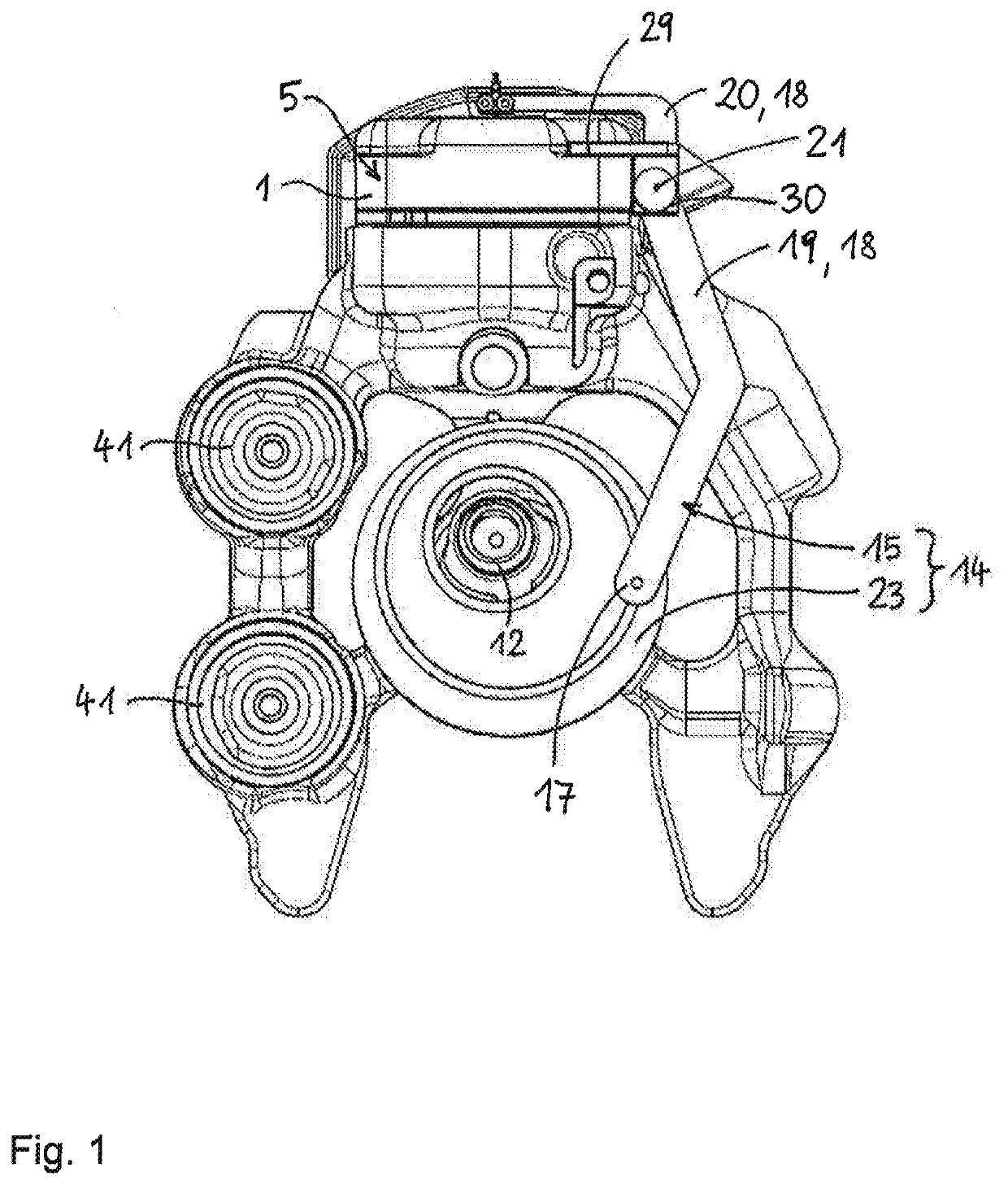
[0049]FIG. 1 shows a plan view of a coolant compressor according to the invention, wherein the components of the coolant compressor are enclosed in a hermetically sealable compressor housing, which is not represented here in order to be able to show the interior of the compressor housing.

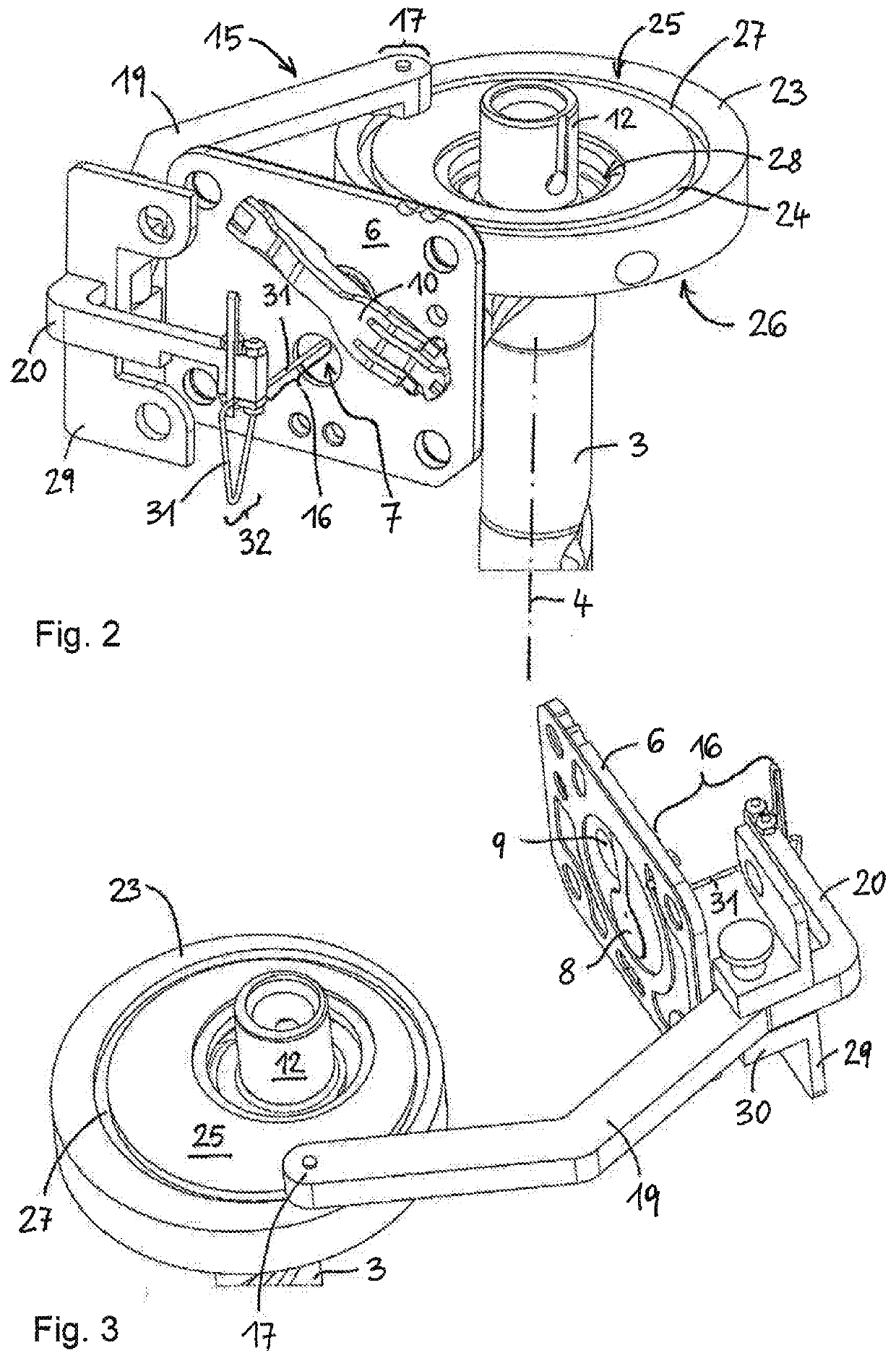
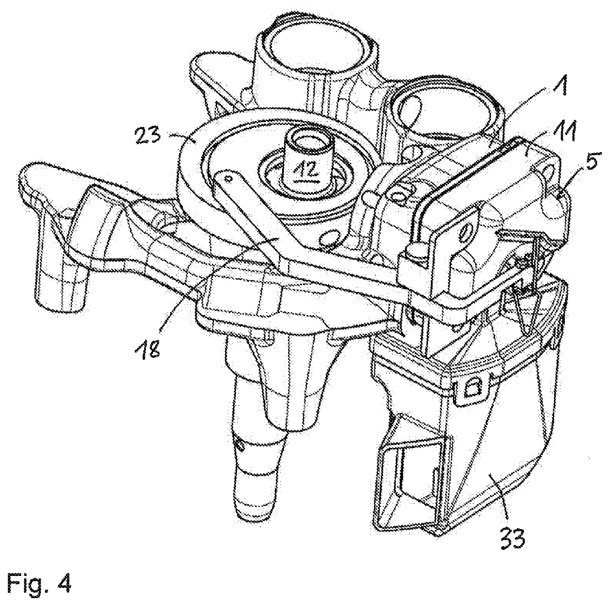
[0050]The coolant compressor comprises an electrical drive unit comprising a stator and a rotor, which is connected for conjoint rotation to a crankshaft 3 (see FIGS. 2 and 3). The crankshaft 3 is drivable by means of the electrical drive unit, and a piston-cylinder unit operatively connected to a crank pin 12 of the crankshaft 3 arranged eccentrically relative to the longitudinal axis 4 of the crankshaft 3 cyclically draws in and compresses coolant. The piston-cylinder unit comprises a cylinder housing 1 enclosing a cylinder, and a piston 2 translationally guided therein (see FIG. 7). The piston 2 is connected via a connecting rod 13 to the crank pin 12 of the crankshaft 3 so that the piston 2 pass...


PUM


Abstract

The invention relates to a coolant compressor comprising an electric drive unit, a cylinder housing (1), a crankshaft (3) which can be driven by the electric drive unit, and a piston (2) that can be driven by the crankshaft (3) and is guided in a working volume of the cylinder housing (1) for cyclically compressing a coolant which can be conveyed via a suction valve into the working volume, said suction valve comprising a suction opening (7) and a valve closure element (8), preferably a valve spring, which closes the suction opening (7) in cycles. The aim of the invention is to ensure a continuous opening movement of the suction valve during the suction cycle. According to the invention, this is achieved by providing an actuation device (14; 15, 23) which is designed to open the valve closure element (8) in cycles.

Description

FIELD OF THE INVENTION[0001]The invention relates to a coolant compressor having an electrical drive unit, a cylinder housing, a crankshaft drivable by the electrical drive unit and a piston drivable by the crankshaft, guided in a working volume of the cylinder housing for cyclical compression of a coolant, which can be conveyed into the working volume via a suction valve comprising a suction opening and a valve-closing element, preferably a valve spring cyclically closing the suction opening.[0002]Generally, a cylinder head arrangement is mounted on the cylinder housing, the cylinder head arrangement comprising a suction opening and a valve-closing element that cyclically closes the suction opening. As a rule, the cylinder head arrangement also comprises a valve plate, which has the suction opening and a pressure opening, as well as a cylinder head cover, which forms a sealed cavity together with the valve plate. The valve-closing element of the suction valve is generally arranged ...

Claims


Application Information

Patent Timeline
IPC IPC(8): F04B35/04F04B39/08
CPCF04B39/08F04B49/06F04B35/04F04B2201/0206F04B35/01F04B39/1073B62D33/02B66F9/07522B66F9/085B66F9/07513B66F9/0755B66F9/10F04B7/0065F04B49/03
Inventor ALMBAUER, RAIMUND
Owner NIDEC GLOBAL APPLIANCE GERMANY GMBH
Why Eureka
Try Eureka