A two-way full-flow turbine

A technology of turbines and flowing water, applied in mechanical equipment, hydroelectric power generation, engine components, etc., can solve the problems of low reverse energy conversion efficiency and large pressure pulsation, so as to improve reverse energy conversion efficiency, reduce pressure arteries, and avoid flow loss effect

Active Publication Date: 2021-01-15
XIAN UNIV OF TECH
View PDF11 Cites 0 Cited by
  • Summary
  • Abstract
  • Description
  • Claims
  • Application Information

AI Technical Summary

Problems solved by technology

[0003] The purpose of the present invention is to provide a two-way full-through flow turbine, which solves the problems of low reverse energy conversion efficiency, forward-biased working condition, and large pressure pulsation in the draft tube of the through-flow turbine in the prior art.

Method used


Image

  • A two-way full-flow turbine
  • A two-way full-flow turbine
  • A two-way full-flow turbine

Examples


Embodiment Construction

[0018] The present invention will be described in detail below in conjunction with the accompanying drawings and specific embodiments.

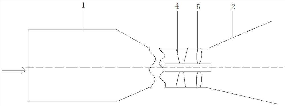
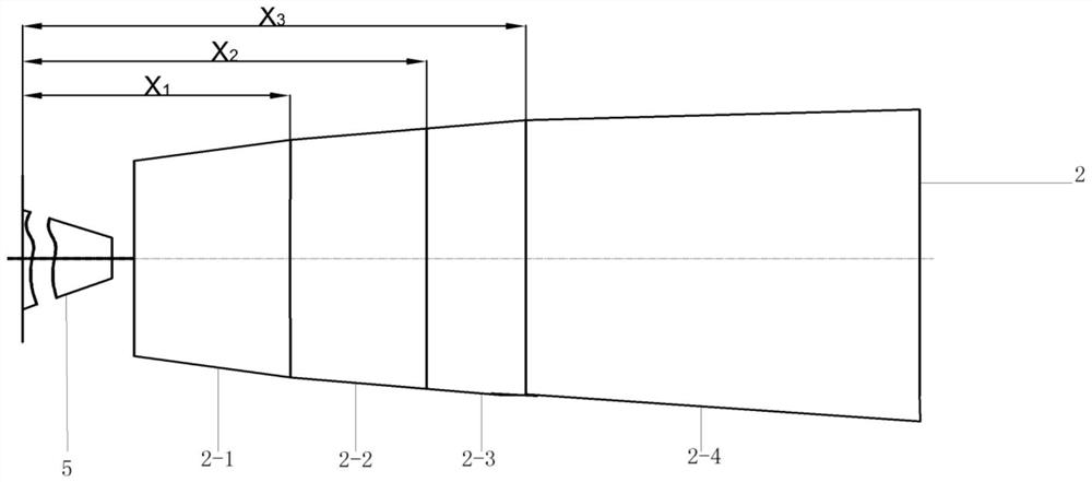
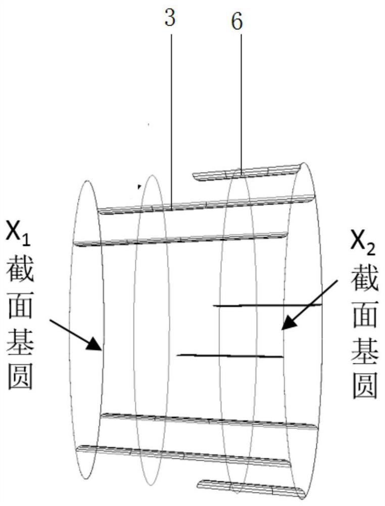
[0019] A two-way full-through flow turbine, such as figure 1 As shown, it includes an inlet pipe 1 and a draft pipe 2 connected in sequence, and movable guide vanes 4 and runners 5 are sequentially arranged on the central axis of the inlet pipe 1 along the direction of water flow; figure 2 As shown, the draft tube 2 includes a first diffuser section 2-1, a second diffuser section 2-2, a third diffuser section 2-3 and a fourth diffuser section 2-4 connected in sequence, as image 3 As shown, the first deflector 3 and the second deflector 6 are connected along the circumference of the inner wall of the second diffusion section 2-2, which is determined by the flow characteristics of the fluid in the draft tube. For draft tubes of different models, The best effect is to place the deflector on the second diffuser section 2-2; the first deflector...


PUM


Abstract

The invention discloses a high-performance two-way full cross flow turbine, which comprises an inlet pipe and a draft pipe connected in sequence, wherein a movable guide vane and a runner are sequentially arranged along a water flow direction on a central axis in the inlet pipe; the draft pipe comprises a first diffusion section, a second diffusion section, a third diffusion section and a fourth diffusion section, which are connected in sequence; a first deflector and a second deflector are connected along the circumference of the inner wall of the second diffusion section, and are equally spaced; the length of the first deflector is equal to that of the second diffusion section, and is greater than that of the second deflector; one end of the second deflector is located at the exit section of the second diffusion section. Unnecessary flow loss is avoided; the second deflector is away from the exit side of the runner, thus preventing from affecting stable operation caused by strong dynamic and static interference between the deflector and an impeller.

Description

technical field [0001] The invention belongs to the technical field of water turbines, and relates to a two-way full-flow water turbine. Background technique [0002] my country has a vast coastline, abundant tidal energy resources, and the low head characteristics of tidal energy, making tubular turbines the first choice for tidal energy development. However, most of the conventional tubular turbines currently used for tidal energy production can only generate electricity in one direction. It is impossible to balance the hydraulic performance of the turbine when it operates in both directions. In order to improve the energy conversion efficiency of low-head tidal energy, the research and development of the two-way fully tubular turbine power generation device has become the mainstream research direction of the tubular turbine. The existing two-way tubular turbine tail The design of the water pipe has caused problems such as low energy utilization efficiency in the reverse wor...

Claims


Application Information

Patent Timeline
Patent Type & Authority Patents(China)
IPC IPC(8): F03B3/18F03B13/26
CPCF03B3/18F03B13/26Y02E10/20
Inventor 冯建军杨红红朱国俊罗兴锜吴广宽
Owner XIAN UNIV OF TECH
Why Eureka
Try Eureka