Adaptive control of motor vehicle powertrain

a technology of motor vehicles and powertrains, applied in electrical control, mechanical equipment, driver input parameters, etc., can solve problems such as difficulties, unfavorable torque map change, and immediate change of engine output torque, and achieve the effect of completing relatively quickly

Active Publication Date: 2017-01-31
JAGUAR LAND ROVER LTD
View PDF15 Cites 1 Cited by
  • Summary
  • Abstract
  • Description
  • Claims
  • Application Information

AI Technical Summary

Benefits of technology

[0027]According to one aspect of the invention, there is provided a method of blending between different characteristics of accelerator pedal position and output torque in a vehicle implemented by a control system, the method comprising the steps of: detecting a first operating mode of a vehicle and applying a source characteristic; detecting a change of operating mode of the vehicle and selecting a target characteristic; blending the source characteristic to the target characteristic at a blending rate, said blending rate being a percentage per unit time of the difference between said characteristics, and providing a progressive change of characteristic throughout the range of accelerator pedal position.
[0031]Thus for blending to a new torque map, with different torque output for a given position of the accelerator pedal, blending gradually changes the shape of the characteristic from that of the first mode to that of a second mode having the target characteristic. The consequence is that a step change in the accelerator pedal position / output torque characteristic at a transition point between the two characteristics is avoided.
[0033]In a refinement the maximum rate of change may be dependent upon a condition of use of the vehicle, such as whether the vehicle is in a high or low transmission range, and is intended to avoid unacceptable rates of change of output torque of a source of propulsion which may affect for example driveability or refinement of the vehicle in certain operating modes.
[0043]The method may include the step of limiting the blending rate such that it does not exceed a maximum value of absolute rate of change of torque.
[0055]When the accelerator pedal reaches the new position P2, blending may in one embodiment continue at the same percentage per unit time of the difference between the source and target characteristics at the new accelerator pedal position P2 unless this value would exceed the maximum allowable absolute value (e.g. 7 Nm·s). If the amount would exceed the maximum allowable value, then in some embodiments, a control system implementing the method converts the maximum allowable value (in this example 7 Nm / s) into a percentage of the difference between the source and target characteristics at the new pedal position, and continues at a blend rate of this percentage of the difference between the source and target characteristics at the new accelerator pedal position P2. Blending thereby effectively continues at the maximum allowable rate. However, importantly, blending proceeds as a percentage per unit time of the difference between source and target characteristics. This has the advantage that if a change in accelerator pedal position P2 subsequently takes place whilst blending is in progress, an instant accelerator pedal progression characteristic may be generated by the control system as described above having a form as a function of pedal position P that is a blend of the forms of the source and target pedal progression characteristics.
[0061]This feature has the advantage that a blend may be completed relatively quickly once a user has moved the throttle pedal.

Problems solved by technology

In between these conditions, a change of map causes an immediate change of engine output torque which may be disconcerting to the vehicle driver, especially if the accelerator pedal is not being moved at the time of change.
A change of torque map may also be undesirable at minimum accelerator position if the behaviour of the vehicle is not as expected when the accelerator pedal is next advanced.
However difficulties may arise if the operating mode is automatically selected in response to a vehicle sensing a change of operating condition.
A consequent instant change in engine response may be disconcerting to the driver, especially if such automatic mode changes are repeated frequently.
A corresponding switch in the reverse direction to mode A results in significant drop in output torque.

Method used


Image

  • Adaptive control of motor vehicle powertrain
  • Adaptive control of motor vehicle powertrain
  • Adaptive control of motor vehicle powertrain

Examples


Embodiment Construction

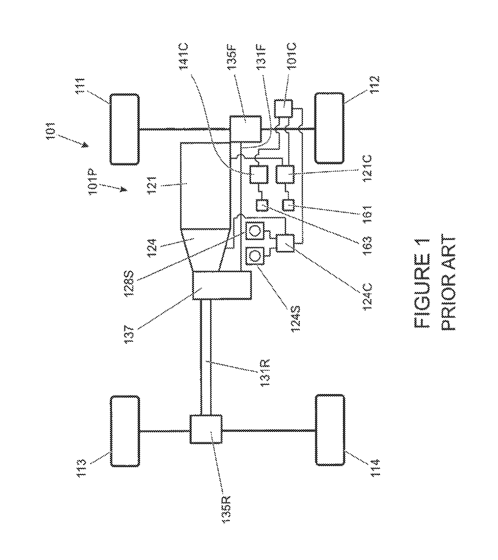
[0084]FIG. 5 is a schematic illustration of a motor vehicle 201 according to an embodiment of the present invention. Like features of the vehicle 201 of FIG. 5 to those of the vehicle 101 of FIG. 1 are shown with like reference numerals prefixed numeral 2 instead of numeral 1. Thus engine 121 of the vehicle 101 of FIG. 1 corresponds to engine 221 of the vehicle 221 of FIG. 5.

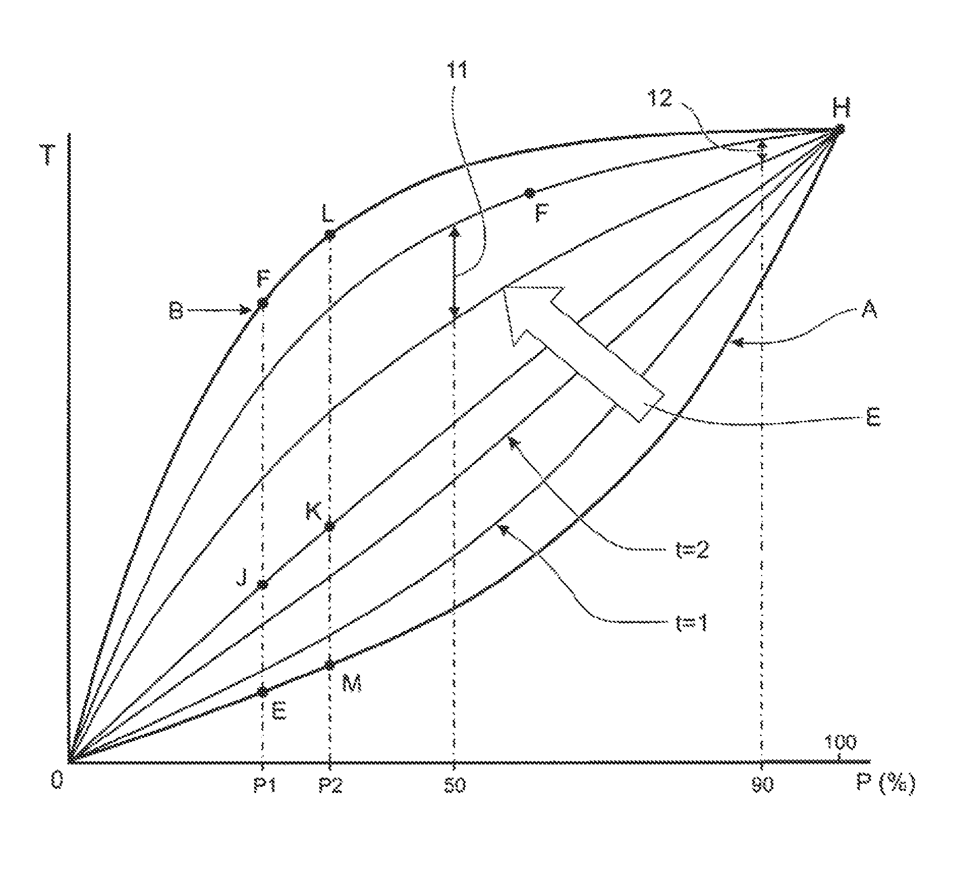
[0085]The vehicle 201 has a VCU 201 programmed with accelerator pedal progression maps that are used to determine engine torque T as a function of accelerator pedal position P.

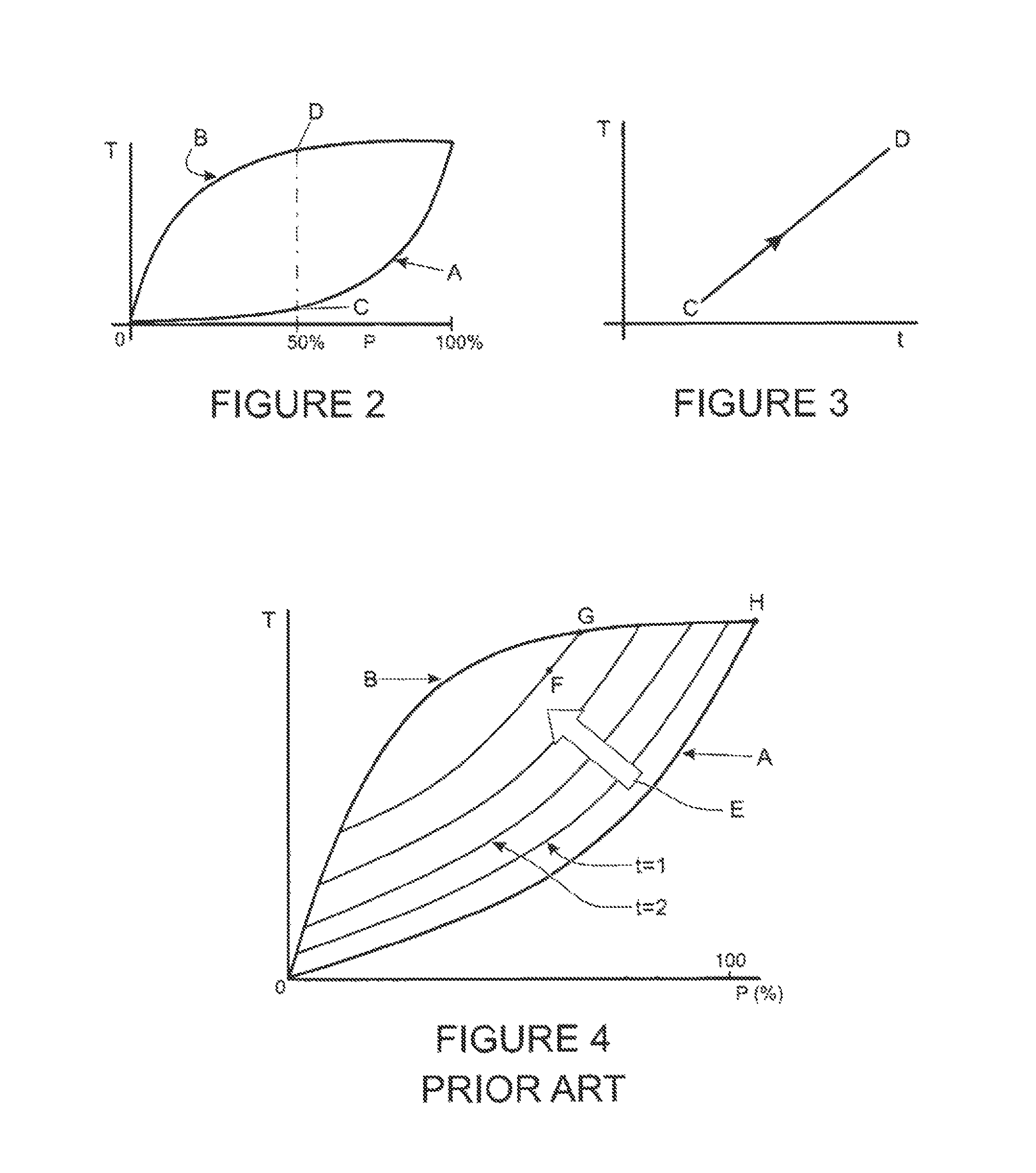
[0086]FIG. 6 shows a plot of engine torque (T) against percentage of maximum accelerator position (P). A cautious characteristic is marked A, and an aggressive characteristic is marked B.

[0087]In the event of a change of vehicle operating mode whereby for example the cautious characteristic is blended to the aggressive characteristic, blending is in the direction of arrow E, and the progress of the blend is indicated at time t=1, t=2 etc.

[...


PUM


Abstract

A method and system is disclosed for blending between torque maps of a source of propulsion of a vehicle. Embodiments of the present invention are particularly applicable to automatic selection of an alternative torque map in response to a change of vehicle operating condition, for example a change of terrain. Blending according to embodiments of the present invention may substantially avoid a step change in response of the source of propulsion as accelerator position is changed.

Description

FIELD OF THE INVENTION[0001]Embodiments of the present invention relate to adaptive control of a powertrain of a motor vehicle. In particular, embodiments of the present invention relate to adaptive control of a source of motive power, for example an internal combustion engine and in particular, but not exclusively, to the response of the engine to an operator command in consequence of a change of engine operating mode. The change of engine operating mode may in turn be related to a change of operating mode of a vehicle in which the engine is installed, for example an operating mode related to the terrain under a vehicle. Aspects of the invention relate to a method, to a system and to a vehicle.BACKGROUND[0002]Internal combustion engines of vehicles may have operating modes which may be selectable by the driver. Thus in some vehicles an economy mode, a normal mode and a sport mode may be provided, each mode having a different engine response to one or more commands of the driver. Ty...

Claims


Application Information

Patent Timeline
Patent Type & Authority Patents(United States)
IPC IPC(8): B60K26/02F02D41/02F02D11/10B60W50/10B60W50/00F02D41/24F02D41/14
CPCB60K26/02B60W50/10F02D11/105F02D41/021B60W2050/0024B60W2050/0026B60W2050/0042B60W2050/0052B60W2540/10B60W2710/0605B60W2710/0611B60W2710/0666B60W2710/0672F02D41/2422F02D2041/1432F02D2200/604B60W30/182B60W2050/0096B60W50/082F02D11/10F02D41/1402B60W2050/0014F02D11/02F02D2200/1002F02D2200/602F02D2200/606F02D2200/702
Inventor DARNELL, PAULHEMES, ELLIOTSTACEY, STEPHEN
Owner JAGUAR LAND ROVER LTD
Why Eureka
Try Eureka