Direct DC converter (DC chopper)

a dc converter and converter technology, applied in the direction of dc-dc conversion, power conversion systems, instruments, etc., can solve the problems of small losses on the switching device, and achieve the effect of saving installation spa

Inactive Publication Date: 2011-06-16
ROBERT BOSCH GMBH
View PDF13 Cites 0 Cited by
  • Summary
  • Abstract
  • Description
  • Claims
  • Application Information

AI Technical Summary

Benefits of technology

[0005]It is therefore an object of the present invention to bring about the increa

Problems solved by technology

This, in turn leads to only slight losse

Method used


Image

  • Direct DC converter (DC chopper)
  • Direct DC converter (DC chopper)
  • Direct DC converter (DC chopper)

Examples


Embodiment Construction

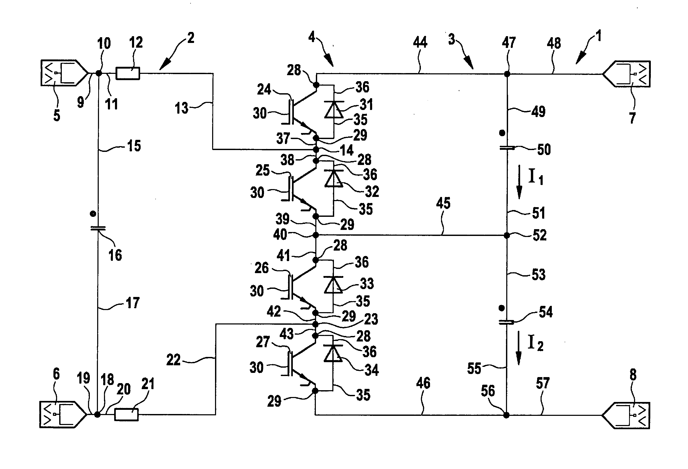
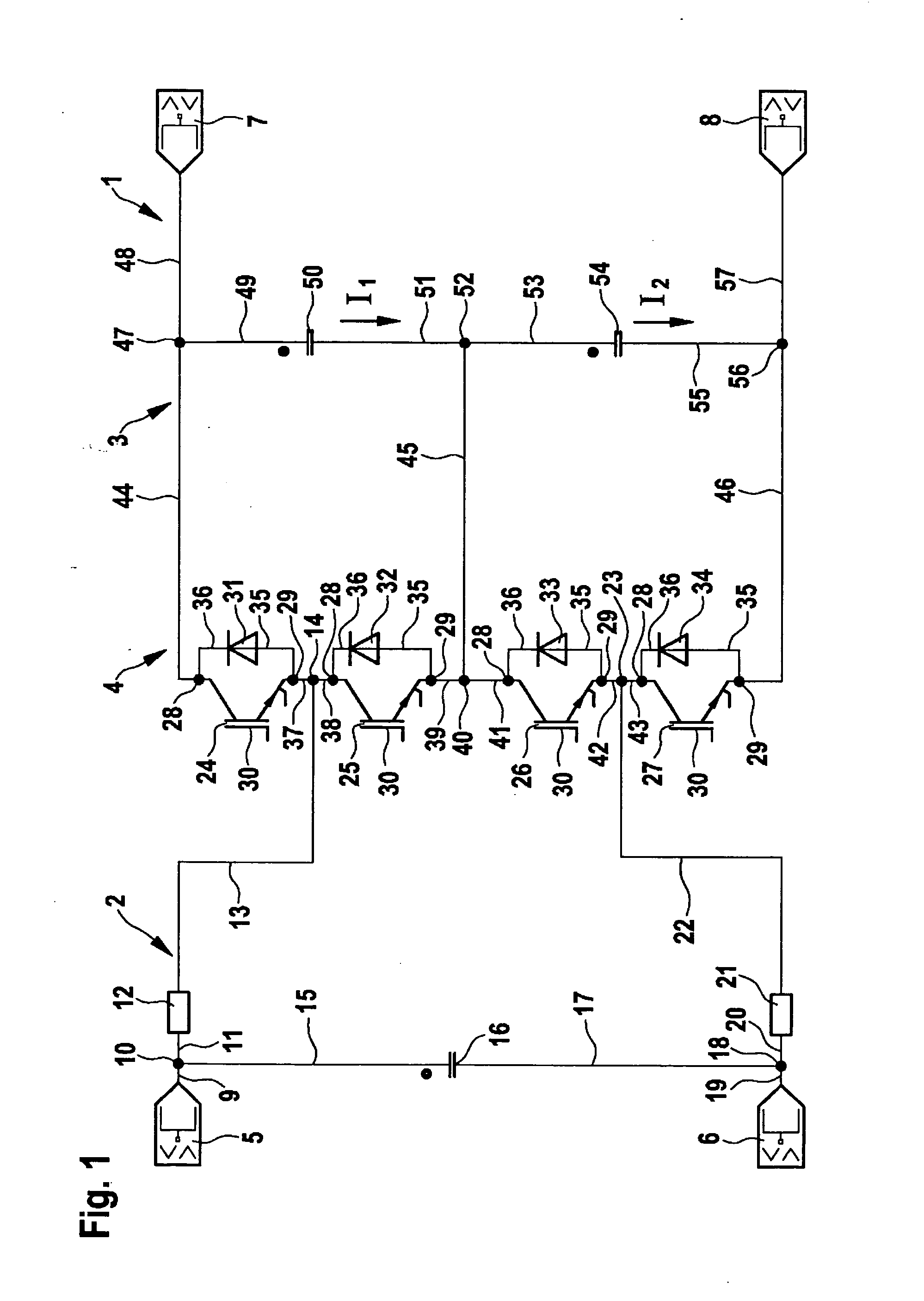
[0018]FIG. 1 shows a DC voltage converter 1 as a circuit diagram. DC voltage converter 1 has a primary side 2 and a secondary side 3, between which a switching device 4 is situated. DC voltage converter 1 has two input terminals 5 and 6, which connect a high voltage battery, that is not shown, to primary side 2, whereby a primary voltage is present at the terminals. On secondary side 3 an inverter, that is not shown, which is preconnected to an electric machine of the hybrid drive of a motor vehicle, is connected via two output terminals 7 and 8, at which a secondary voltage is present. Starting from input terminal 5, a line 9 runs to a node 10. From node 10, a line 11 runs to an inductor 12, which is connected to a connecting point 14, using a line 13. Starting from node 10, an additional line 15 runs to a primary capacitor 16, which is connected to a node 18 via a second line 17. Node 18 leads to input terminal 6 via line 19. Via a third line 20, node 18 is connected to an inducto...


PUM


Abstract

A DC voltage converter has a primary side and a secondary side coupled galvanically to the primary side. The primary side has at least one inductor, and the secondary side has at least two secondary capacitors connected in series. A controllable electronic switching device is situated between the primary side and the secondary side. In a first operating mode, depending on the switching position, the secondary capacitors are charged one after the other via the inductor, and the respective charging process ends approximately at the zero crossing of the respective charging current.

Description

BACKGROUND OF THE INVENTION[0001]1. Field of the Invention[0002]The present invention relates to a DC-DC converter having a primary side and a secondary side that is coupled galvanically to the primary side.[0003]2. Description of Related Art[0004]To supply electric machines of hybrid drives, high voltage batteries or traction batteries are used, to which an inverter is postconnected. A nominal voltage of high voltage batteries is approximately 100 V-300 V. Based on the battery's internal resistance, a voltage at an intermediate circuit of the inverter, depending on the operating type, as a motor or as a generator, of the electric machine, and depending on the transmitted electric power, amounts to between ca. 50 V and 400 V. A high intermediate voltage leads to cost savings and space savings in the inverter, in wiring harnesses used in the motor vehicle and in the electric machine. In order to achieve these, a single-phase or multi-phase boost chopper is used for increasing the vol...

Claims


Application Information

Patent Timeline
IPC IPC(8): G05F3/08
CPCH02M3/158H02M1/08H02J2207/50
Inventor SCHOENKNECHT, ANDREAS
Owner ROBERT BOSCH GMBH
Why Eureka
Try Eureka