Power feeding coil unit and wireless power transmission device

a technology of power transmission device and feeding coil, which is applied in the direction of transformer/inductance magnetic core, charging station, transportation and packaging, etc., can solve the problems of reducing power transmission efficiency and potential electromagnetic interference, and achieve the effect of improving power transmission efficiency, enhancing magnetic field, and easily generating magnetic flux

Active Publication Date: 2017-01-31
TDT
View PDF38 Cites 2 Cited by
  • Summary
  • Abstract
  • Description
  • Claims
  • Application Information

AI Technical Summary

Benefits of technology

[0008]Accordingly, an embodiment of the present invention provides a power feeding coil unit and a wireless power transmission device to prevent or minimize a reduction in power transmission efficiency while reducing an unwanted leakage magnetic field formed in a location away from a power feeding coil.

Problems solved by technology

In this case, the strength of the unwanted leakage magnetic field due to the leakage magnetic flux also increases, raising a concern of potentially inducing electromagnetic interference which might affect nearby electronic equipment and so forth.
However, in the technique disclosed in Japanese Unexamined Patent Application Publication No. 09-74034, since the magnetic flux created by the coil for power transmission interlinks with the noise canceling coil, even a magnetic flux that would contribute to power transmission might also be canceled, resulting in a reduction in power transmission efficiency.

Method used


Image

  • Power feeding coil unit and wireless power transmission device
  • Power feeding coil unit and wireless power transmission device
  • Power feeding coil unit and wireless power transmission device

Examples


first embodiment

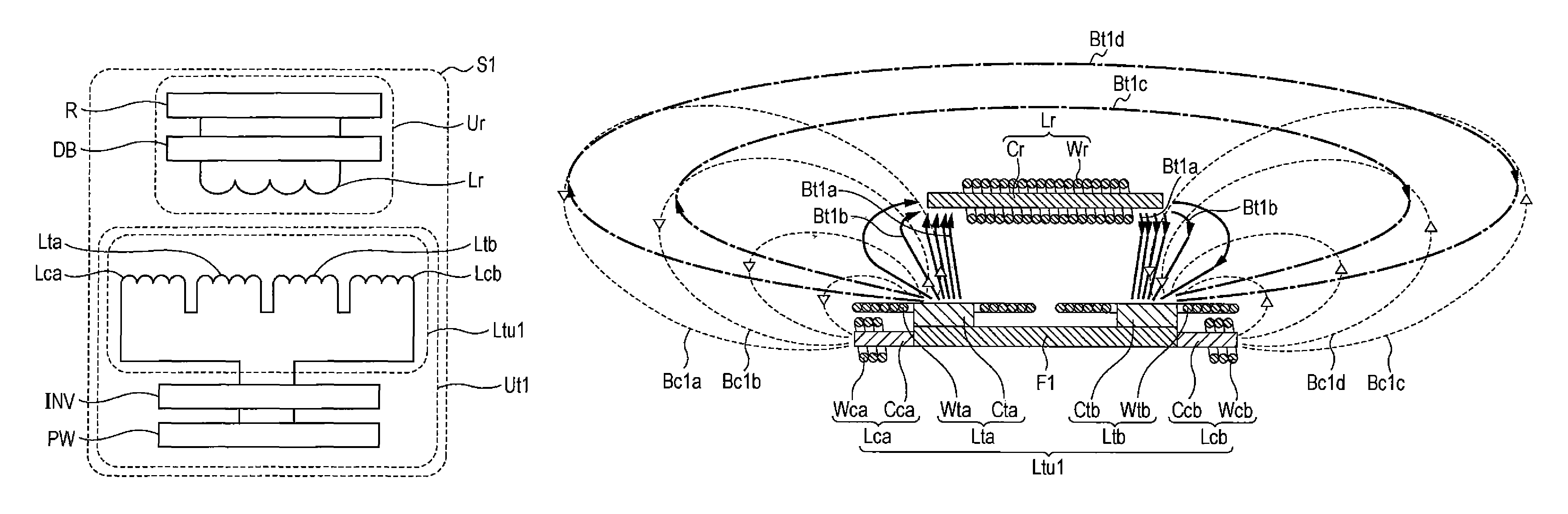
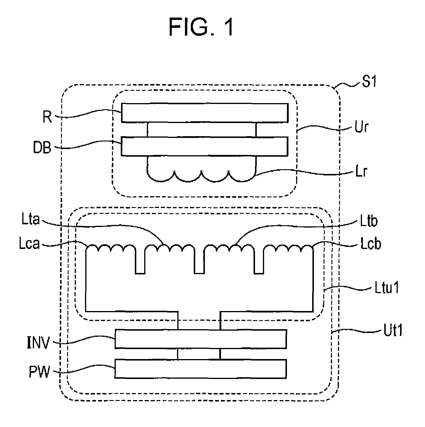
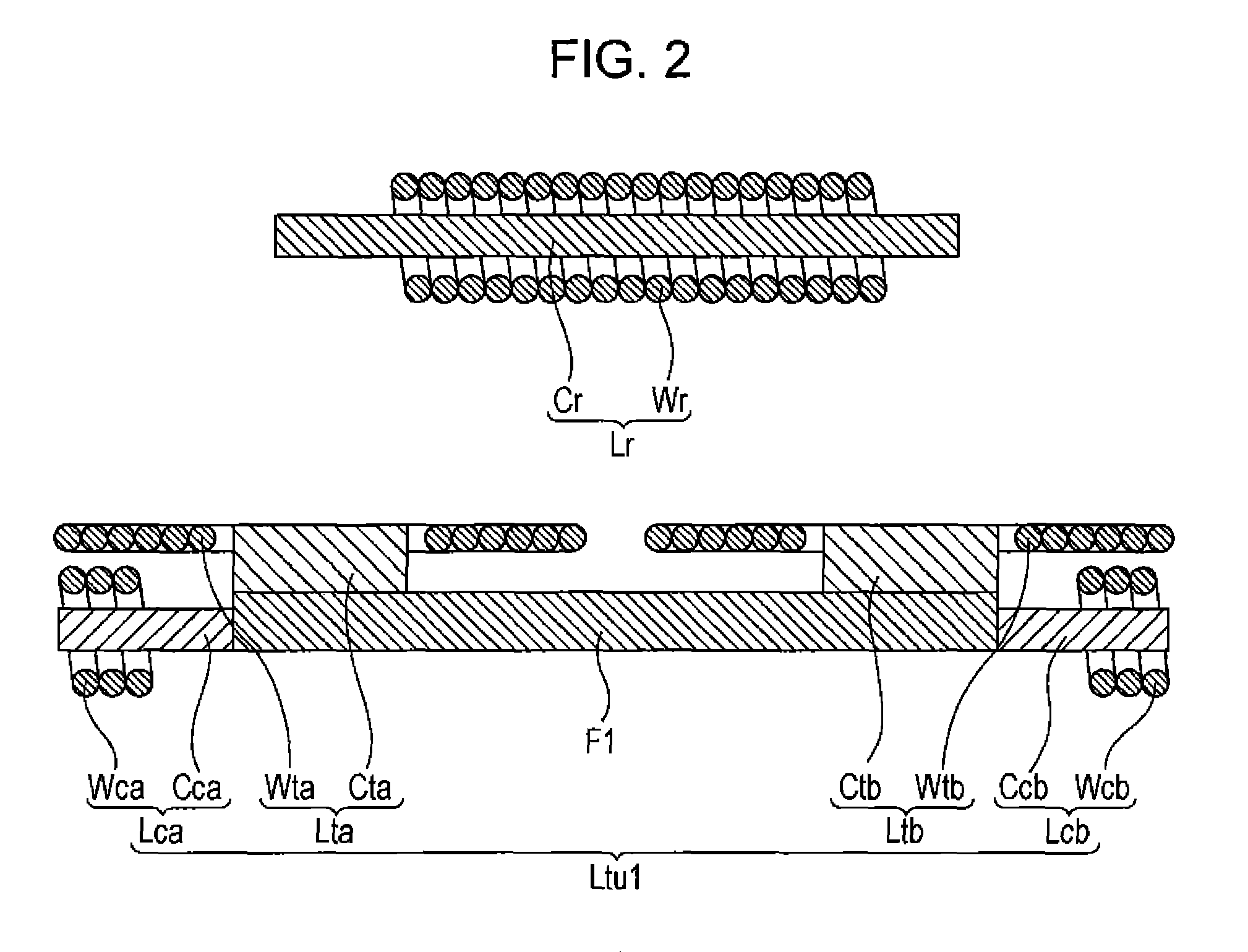
[0042]First, a configuration of a wireless power transmission device S1 according to a first embodiment of the present invention will be described with reference to FIG. 1 and FIG. 2. FIG. 1 is a system configuration diagram illustrating a wireless power transmission device according to the first embodiment of the present invention together with a load. FIG. 2 is a cross-sectional view illustrating a power feeding coil unit according to the first embodiment of the present invention together with a power receiving coil.

[0043]As illustrated in FIG. 1, the wireless power transmission device S1 includes a wireless power feeding device Ut1 and a wireless power receiving device Ur.

[0044]The wireless power feeding device Ut1 includes a power source PW, an inverter INV, and a power feeding coil unit Ltu1. The power source PW supplies direct-current (DC) power to the inverter INV, described below. The power source PW is not limited to any particular one, and may be any power source that outp...

second embodiment

[0069]Next, a configuration of a wireless power transmission device S2 according to a second embodiment of the present invention will be described with reference to FIG. 4 and FIG. 5. FIG. 4 is a system configuration diagram illustrating a wireless power transmission device according to the second embodiment of the present invention together with a load. FIG. 5 is a cross-sectional view illustrating a power feeding coil unit according to the second embodiment of the present invention together with a power receiving coil.

[0070]As illustrated in FIG. 4, the wireless power transmission device S2 includes a wireless power feeding device Ut2 and a wireless power receiving device Ur.

[0071]The wireless power feeding device Ut2 includes a power source PW, an inverter INV, and a power feeding coil unit Ltu2. The configuration of the power source PW and the inverter INV is similar to that in the wireless power transmission device S1 according to the first embodiment. The wireless power transm...

third embodiment

[0087]Next, a configuration of a wireless power transmission device S3 according to a third embodiment of the present invention will be described with reference to FIG. 7 and FIG. 8. FIG. 7 is a system configuration diagram illustrating a wireless power transmission device according to the third embodiment of the present invention together with a load. FIG. 8 is a cross-sectional view illustrating a power feeding coil unit according to the third embodiment of the present invention together with a power receiving coil.

[0088]As illustrated in FIG. 7, the wireless power transmission device S3 includes a wireless power feeding device Ut3 and a wireless power receiving device Ur.

[0089]The wireless power feeding device Ut3 includes a power source PW, an inverter INV, and a power feeding coil unit Ltu3. The configuration of the power source PW and the inverter INV is similar to that in the wireless power transmission device S1 according to the first embodiment. The wireless power transmiss...


PUM

PropertyMeasurementUnit
diameteraaaaaaaaaa
diameteraaaaaaaaaa
thicknessaaaaaaaaaa

Abstract

A power feeding coil unit includes a power feeding coil, and an auxiliary coil. The auxiliary coil is arranged not to interlink with a magnetic flux that interlinks with a power receiving coil that is arranged to face the power feeding coil during power feeding. An axial direction of the auxiliary coil is nonparallel to an opposing direction of the power feeding coil and the power receiving coil. A direction of circulation of a magnetic flux generated by the auxiliary coil is opposite to a direction of circulation of a magnetic flux generated by the power feeding coil.

Description

BACKGROUND OF THE INVENTION[0001]1. Field of the Invention[0002]The present invention relates to a power feeding coil unit and a wireless power transmission device for wireless transmission of power.[0003]2. Description of the Related Art[0004]Wireless power transmission technology that utilizes an electromagnetic induction effect between a primary (power feeding) coil and a secondary (power receiving) coil that face each other to transmit power without any mechanical contact such as a cable has attracted attention recently. There has been an increasing demand for the development of a technology that allows high-efficiency and low-loss power transmission.[0005]In this situation, the issue of an unwanted leakage magnetic field formed around the power feeding coil due to the leakage magnetic flux of the power feeding coil has been gaining attention. For example, in the application of wireless power transmission technology to chargers for power electronic devices such as electric vehic...

Claims


Application Information

Patent Timeline
Patent Type & Authority Patents(United States)
IPC IPC(8): H01F5/00H02J7/02H02J7/00B60L11/00H01F27/38H01F37/00H01F38/00H01F27/34H01F27/28H01F38/14H02J5/00H01F27/24H01F27/42
CPCH01F27/346B60L11/00H01F5/00H01F27/24H02J50/10H01F27/28H01F27/38H01F27/42H01F37/00H01F38/00H01F38/14H02J5/005H02J7/0042H02J7/025Y02T90/12Y02T90/14B60L2270/147B60L53/126B60L53/122Y02T10/7072Y02T10/70H02J50/402H02J50/005H02J50/70
Inventor CHIYO, NORITAKAKAMONO, TAKESHIFUKUZAWA, NARUTOSHIMATSUURA, TOSHINORINISHIYAMA, TETSUYA
Owner TDT
Why Eureka
Try Eureka