Power feeding coil unit and wireless power transmission device

a technology of power feeding coil and wireless transmission, which is applied in the direction of transformer/inductance magnetic core, charging station, transportation and packaging, etc., can solve the problems of reducing power transmission efficiency and potential electromagnetic interference, and achieve the effect of enhancing a part of a magnetic field, facilitating the generation of magnetic flux, and reducing the reduction of power transmission efficiency

Active Publication Date: 2015-05-28
TDK CORPARATION
View PDF4 Cites 22 Cited by
  • Summary
  • Abstract
  • Description
  • Claims
  • Application Information

AI Technical Summary

Benefits of technology

[0008]Accordingly, an embodiment of the present invention provides a power feeding coil unit and a wireless power transmission device to prevent or minimize a reduction in power transmission efficiency while reducing an unwanted leakage magnetic field formed in a location away from a power feeding coil.

Problems solved by technology

In this case, the strength of the unwanted leakage magnetic field due to the leakage magnetic flux also increases, raising a concern of potentially inducing electromagnetic interference which might affect nearby electronic equipment and so forth.
However, in the technique disclosed in Japanese Unexamined Patent Application Publication No. 09-74034, since the magnetic flux created by the coil for power transmission interlinks with the noise canceling coil, even a magnetic flux that would contribute to power transmission might also be canceled, resulting in a reduction in power transmission efficiency.

Method used


Image

  • Power feeding coil unit and wireless power transmission device
  • Power feeding coil unit and wireless power transmission device
  • Power feeding coil unit and wireless power transmission device

Examples


first embodiment

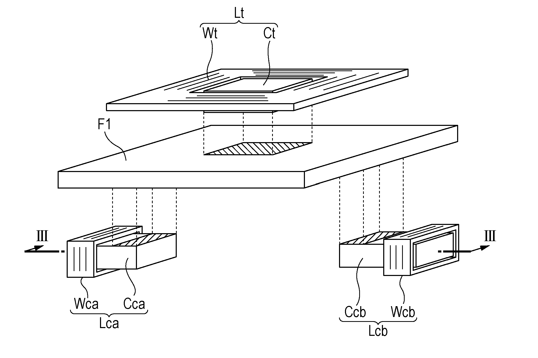
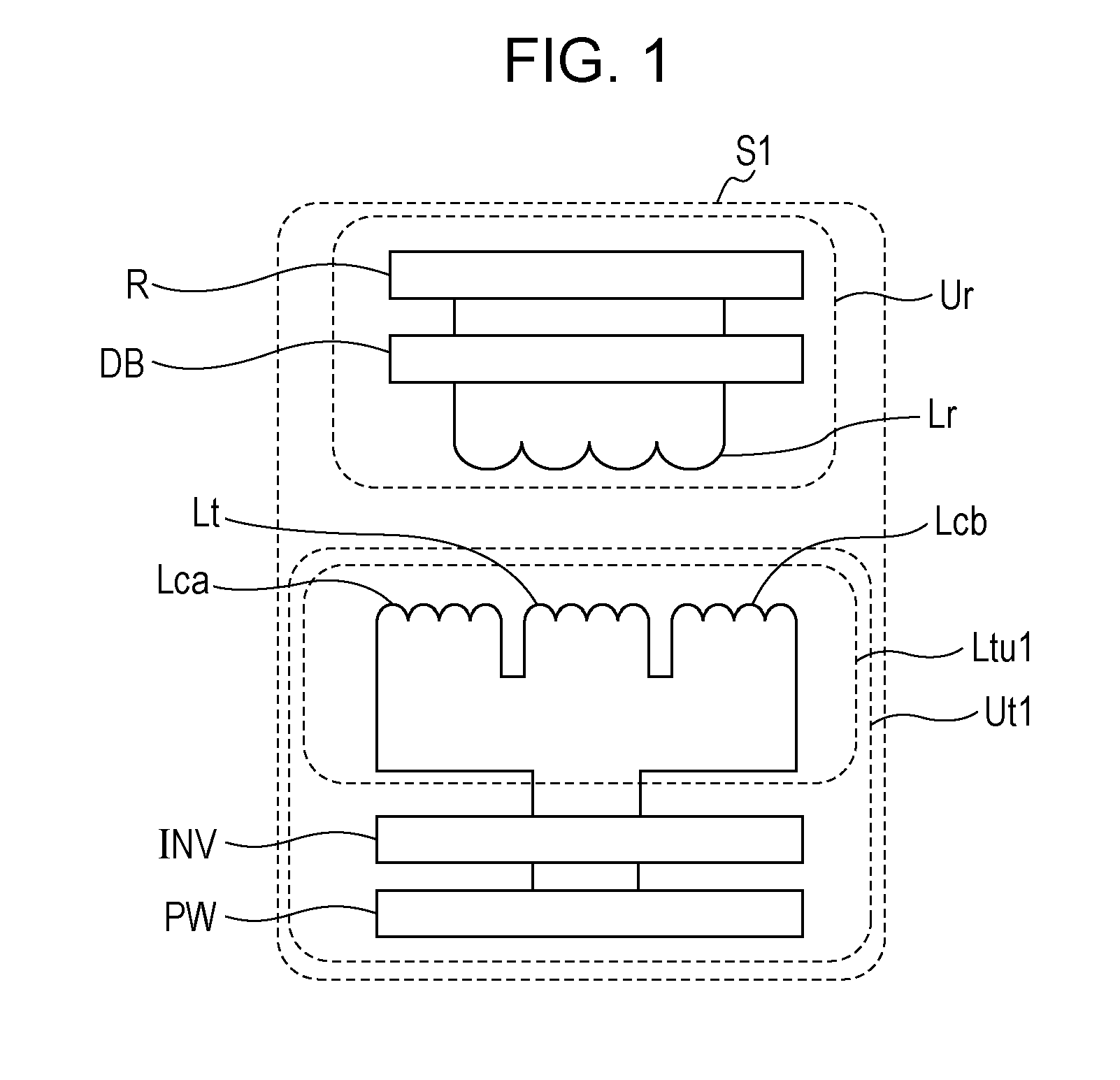
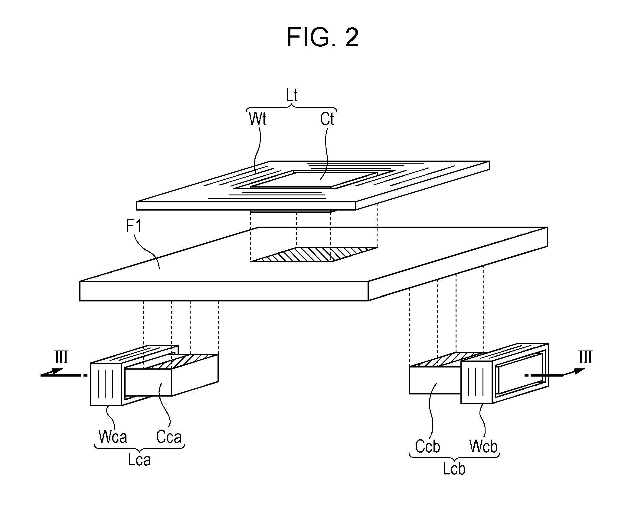
[0036]First, a configuration of a wireless power transmission device S1 according to a first embodiment of the present invention will be described with reference to FIGS. 1 to 3. FIG. 1 is a system configuration diagram illustrating a wireless power transmission device according to the first embodiment of the present invention together with a load. FIG. 2 is an exploded perspective view of a power feeding coil unit according to the first embodiment of the present invention. FIG. 3 is a schematic cross-sectional view of the power feeding coil unit, taken along line III-III in FIG. 2, together with a power receiving coil.

[0037]As illustrated in FIG. 1, the wireless power transmission device S1 includes a wireless power feeding device Ut1 and a wireless power receiving device Ur. The wireless power feeding device Ut1 includes a power source PW, an inverter INV, and a power feeding coil unit Ltu1. The wireless power receiving device Ur includes a power receiving coil Lr and a rectifier ...

second embodiment

[0058]Next, a configuration of a wireless power transmission device S2 according to a second embodiment of the present invention will be described with reference to FIG. 5 and FIG. 6. FIG. 5 is a system configuration diagram illustrating a wireless power transmission device according to the second embodiment of the present invention together with a load. FIG. 6 is a schematic cross-sectional view of a power feeding coil unit according to the second embodiment of the present invention together with first and second power receiving coils, which corresponds to the schematic cross-sectional view of the power feeding coil unit according to the first embodiment illustrated in FIG. 3, taken along line III-III in FIG. 2.

[0059]As illustrated in FIG. 5, the wireless power transmission device S2 includes a wireless power feeding device Ut1 and a wireless power receiving device Ur2. The wireless power feeding device Ut1 includes a power source PW, an inverter INV, and a power feeding coil unit ...

third embodiment

[0070]Next, a configuration of a wireless power transmission device S3 according to a third embodiment of the present invention will be described with reference to FIGS. 8, 9, 10A, and 10B. FIG. 8 is a system configuration diagram illustrating a wireless power transmission device according to the third embodiment of the present invention together with a load. FIG. 9 is an exploded perspective view of a power feeding coil unit according to the third embodiment of the present invention. FIG. 10A is a schematic cross-sectional view of the power feeding coil unit, taken along line XA-XA in FIG. 9, together with a power receiving coil. FIG. 10 is a schematic cross-sectional view of the power feeding coil unit, taken along line XB-XB in FIG. 9, together with the power receiving coil.

[0071]As illustrated in FIG. 8, the wireless power transmission device S3 includes a wireless power feeding device Ut2 and a wireless power receiving device Ur. The wireless power feeding device Ut2 includes a...


PUM

PropertyMeasurementUnit
diameteraaaaaaaaaa
diameteraaaaaaaaaa
thicknessaaaaaaaaaa

Abstract

A power feeding coil unit includes a power feeding coil, and first and second auxiliary coils located outside of the region defined by a wire of the power feeding coil. The axis of the first auxiliary coil and the axis of the second auxiliary coil are substantially perpendicular to the axis of the power feeding coil. The power feeding coil and the first and second auxiliary coils simultaneously generate respective magnetic fluxes, each of which interlinks the corresponding one of the power feeding coil and the first and second auxiliary coils in a direction from the center to the outside of the power feeding coil unit.

Description

BACKGROUND OF THE INVENTION[0001]1. Field of the Invention[0002]The present invention relates to a power feeding coil unit and a wireless power transmission device for wireless transmission of power.[0003]2. Description of the Related Art[0004]Wireless power transmission technology that utilizes an electromagnetic induction effect between a primary (power feeding) coil and a secondary (power receiving) coil that face each other to transmit power without any mechanical contact such as a cable has attracted attention recently. There has been an increasing demand for the development of a technology that allows high-efficiency and low-loss power transmission.[0005]In this situation, the issue of an unwanted leakage magnetic field formed around the power feeding coil due to the leakage magnetic flux of the power feeding coil has been gaining attention. For example, in the application of wireless power transmission technology to chargers for power electronic devices such as electric vehic...

Claims


Application Information

Patent Timeline
Patent Type & Authority Applications(United States)
IPC IPC(8): H01F27/34H01F27/28H01F27/24H02J5/00H01F38/14
CPCH01F27/346H01F27/24H01F27/28H02J5/005H01F27/38H01F38/14Y02T10/7072Y02T90/14H01F27/2871B60L53/126Y02T10/70H02J50/70H02J50/10Y02T90/12
Inventor CHIYO, NORITAKATERASAKI, YASUHIRONISHIYAMA, TETSUYA
Owner TDK CORPARATION
Why Eureka
Try Eureka