Power feeding coil unit and wireless power transmission device

Active Publication Date: 2015-05-28
TDK CORPARATION
View PDF4 Cites 13 Cited by
  • Summary
  • Abstract
  • Description
  • Claims
  • Application Information

AI Technical Summary

Benefits of technology

[0012]In the power feeding coil unit according to the aspect of the present invention, furthermore, the axes of the first and second auxiliary coils are not aligned with the axis of the power feeding coil. The arrangement described above makes it difficult for the magnetic fluxes generated by the first and second auxiliary coils to interlink with the power feeding coil, preventing the magnetic flux generated by the power feeding coil, which contributes to power transmission, from being canceled by the magnetic flux generated by the first and second auxiliary coils. As a result, a reduction in power transmission efficiency may be prevented or minimized. Accordingly, a reduction in power transmission efficiency may be prevented or minimized with a reduction in an unwanted leakage magnetic field formed in a location away from a power feeding coil.
[0013]Preferably, the axes of the first and second auxiliary coils are substantially perpendicular to the power feeding direction of the power feeding coil. That is, the axes of the first and second auxiliary coils are substantially perpendicular to the opposing direction of the power feeding coil and the power receiving coil. In this case, the first and second auxiliary coils more facilitate the generation of a magnetic flux that circulates also in a location away from the first and second auxiliary coils. As a result, the effect of reducing an unwanted leakage magnetic field formed in a location away from a power feeding coil may further be enhanced.
[0014]Preferably, the first and second auxiliary coils are located on a rear side of the power feeding coil. That is, the first and second auxiliary coils are arranged on the opposite to a side of the power feeding coil facing the power receiving coil. In this case, the first and second auxiliary coils more easily generate a magnetic flux that enhances a part of a magnetic field between the power feeding coil and the power receiving coil. That is, the magnetic flux generated by the power feeding coil and the magnetic flux generated by the first and second auxiliary coils are oriented in substantially the same direction bet

Problems solved by technology

In this case, the strength of the unwanted leakage magnetic field due to the leakage magnetic flux also increases, raising a concern of potentially inducing electromagnetic interference which might affect nearby electronic equipment and so forth.
However, in the technique disclosed in Japanese Unexamine

Method used


Image

  • Power feeding coil unit and wireless power transmission device
  • Power feeding coil unit and wireless power transmission device
  • Power feeding coil unit and wireless power transmission device

Examples


Embodiment Construction

[0025]An embodiment of the present invention will be described in detail with reference to the drawings. In the following description, substantially the same elements or elements having substantially the same function are given the same numerals or signs, and are not described again.

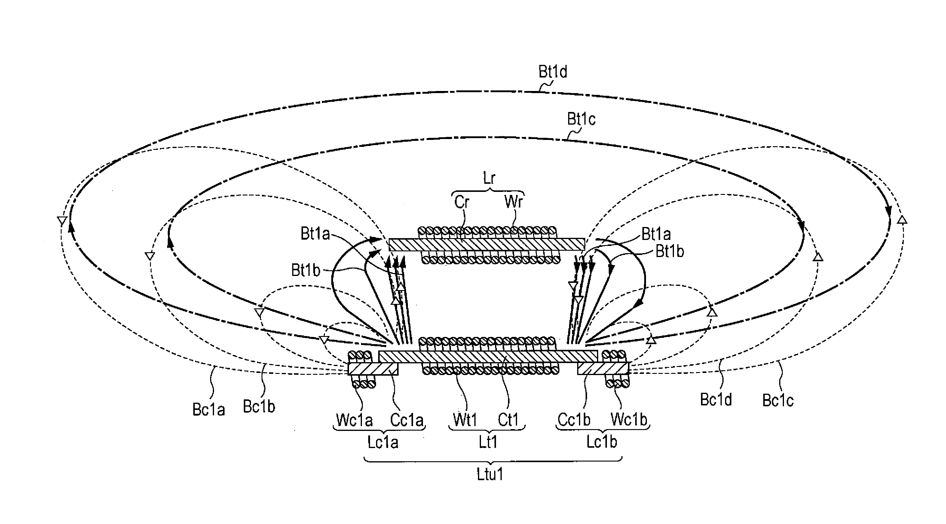
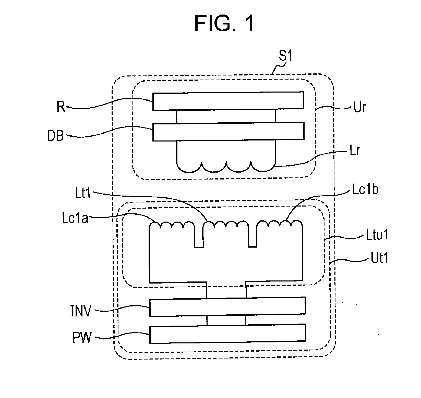
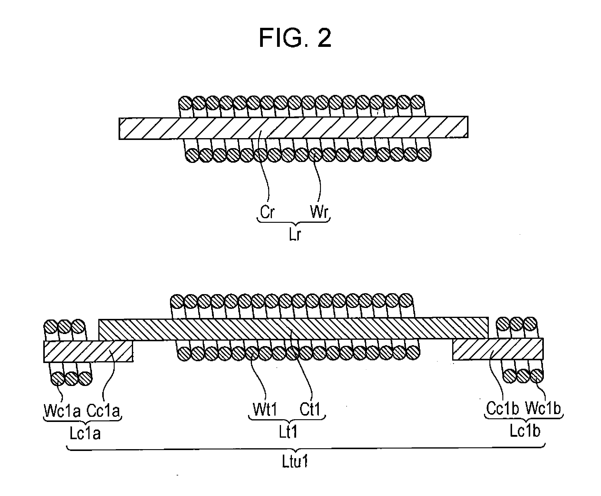
[0026]First, a configuration of a wireless power transmission device S1 according to a preferred embodiment of the present invention will be described with reference to FIGS. 1 and 2. FIG. 1 is a system configuration diagram illustrating a wireless power transmission device according to the preferred embodiment of the present invention together with a load. FIG. 2 is a cross-sectional view illustrating a power feeding coil unit according to the preferred embodiment of the present invention together with a power receiving coil.

[0027]As illustrated in FIG. 1, the wireless power transmission device S1 includes a wireless power feeding device Ut1 and a wireless power receiving device Ur.

[0028]The wireless po...


PUM


Abstract

A power feeding coil unit includes a power feeding coil, and first and second auxiliary coils arranged so that a wire of the first auxiliary coil and a wire of the second auxiliary coil do not overlap a wire of the a power feeding coil when viewed from a direction perpendicular to an axial direction of the power feeding coil. A direction of circulation of a magnetic flux generated by the first auxiliary coil and a magnetic flux generated by the second auxiliary coil are opposite to a direction of circulation of a magnetic flux generated by the power feeding coil. An axes of the first and second auxiliary coils are substantially perpendicular to a power feeding direction of the power feeding coil, and are not aligned with the axis of the power feeding coil.

Description

BACKGROUND OF THE INVENTION[0001]1. Field of the Invention[0002]The present invention relates to a power feeding coil unit and a wireless power transmission device for wireless transmission of power.[0003]2. Description of the Related Art[0004]Wireless power transmission technology that utilizes an electromagnetic induction effect between a primary (power feeding) coil and a secondary (power receiving) coil that face each other to transmit power without any mechanical contact such as a cable has attracted attention recently. There has been an increasing demand for the development of a technology that allows high-efficiency and low-loss power transmission.[0005]In this situation, the issue of an unwanted leakage magnetic field formed around the power feeding coil due to the leakage magnetic flux of the power feeding coil has been gaining attention. For example, in the application of wireless power transmission technology to chargers for power electronic devices such as electric vehic...

Claims


Application Information

Patent Timeline
IPC IPC(8): H01F27/34H01F27/28H02J5/00
CPCH01F27/346H01F27/28H02J5/005H01F3/10H01F27/38H01F38/14H01F27/24H02J50/10H02J50/70
Inventor CHIYO, NORITAKANISHIYAMA, TETSUYA
Owner TDK CORPARATION
Why Eureka
Try Eureka