
Iliac connector, connector head, spinal fixation system and method of stabilizing a spine

a technology of spinal fixation system and iliac connector, which is applied in the field of iliac connector, connector head, spinal fixation system and method of stabilizing a spine, can solve the problems of inability to correctly absorb shock, minute, but yet significant motion loss, and unnoticed iliac mechanism of patients, so as to prevent screw pull out, and absorb shock better

Active Publication Date: 2017-02-07
LIGNE
View PDF55 Cites 19 Cited by
  • Summary
  • Abstract
  • Description
  • Claims
  • Application Information

AI Technical Summary

Benefits of technology

[0019]Since the connecting rod is more flexible than titanium, movement of the ilium relative to the sacrum is still possible. However the rod gives sufficient stabilization between these two parts. The rod allows a very low deformation in longitudinal direction but still allows sufficient bending and rotation around its longitudinal direction. It also allows, when coupled with a spinal rod a coupled motion.
[0052]This method enables the surgeon to choose or correct for example the placement of the iliac bone screw at a very late stage of the surgery after the longitudinal elements and pedicle screws have been placed in it is inter-operatively decided to extend the fusion. Also other parts of the spinal fixation system can be rearranged and their relationship to other parts can be changed within a small range at a late stage.

Problems solved by technology

While this is an extensive operation with potentially serious complications, a spinal fusion can be considered a lesser evil than the problem the surgeon must solve.
This mechanism is often unnoticed by the patient until it is disrupted or gone.
Since the posterior ligaments are removed and the joint blocked, a minute, but yet significant motion is lost.
Shocks can not be absorbed correctly.
Shocks are uncomfortable and over time can degenerate the surrounding joints of the hips and spine.

Method used


Image

  • Iliac connector, connector head, spinal fixation system and method of stabilizing a spine
  • Iliac connector, connector head, spinal fixation system and method of stabilizing a spine
  • Iliac connector, connector head, spinal fixation system and method of stabilizing a spine

Examples


Embodiment Construction

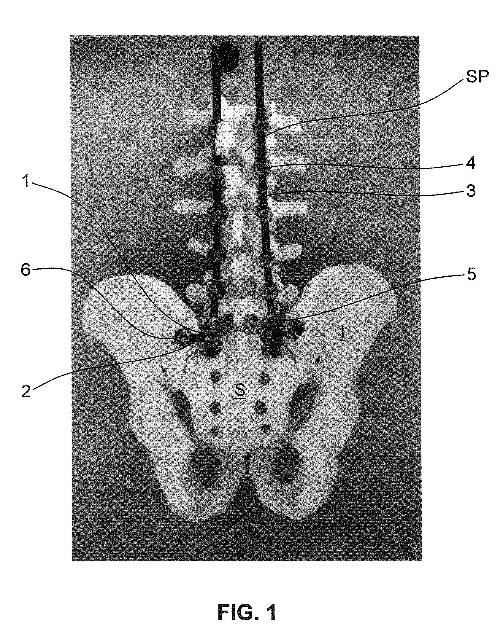
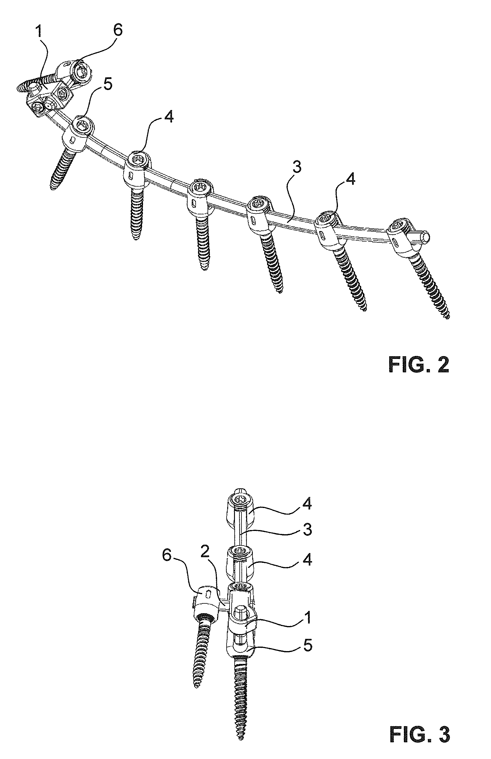
[0075]FIGS. 1 to 3 show a first embodiment of an inventive spinal fixation system using an inventive iliac connector and an inventive connector head.

[0076]The spinal fixation system comprises one preferably two spinal rods 3 extending along a spine SP and being fixed to one or more vertebrae of the spine SP. The spinal rod 3 is preferably curved. Known pedicle bone screws 4 are used as anchors for the fixation to the vertebrae, wherein these spinal bone screws 4 preferably have known tulip heads. The spinal bone screws 4 with the tulips are preferably made of titanium.

[0077]The spinal rod 3 is preferably made of a more flexible material, such as a filament composite material. Preferably it is made of carbon filaments encapsulated in a polymer matrix, such as PEKEKK or PEEK. The composite material preferably comprises of about 66.6% (weight %) of carbon fibers and of about 33.3% polyether-ketoneetherketoneketone (PEKEKK) as encapsulating matrix. The fibres or filaments are preferably...


PUM


Abstract

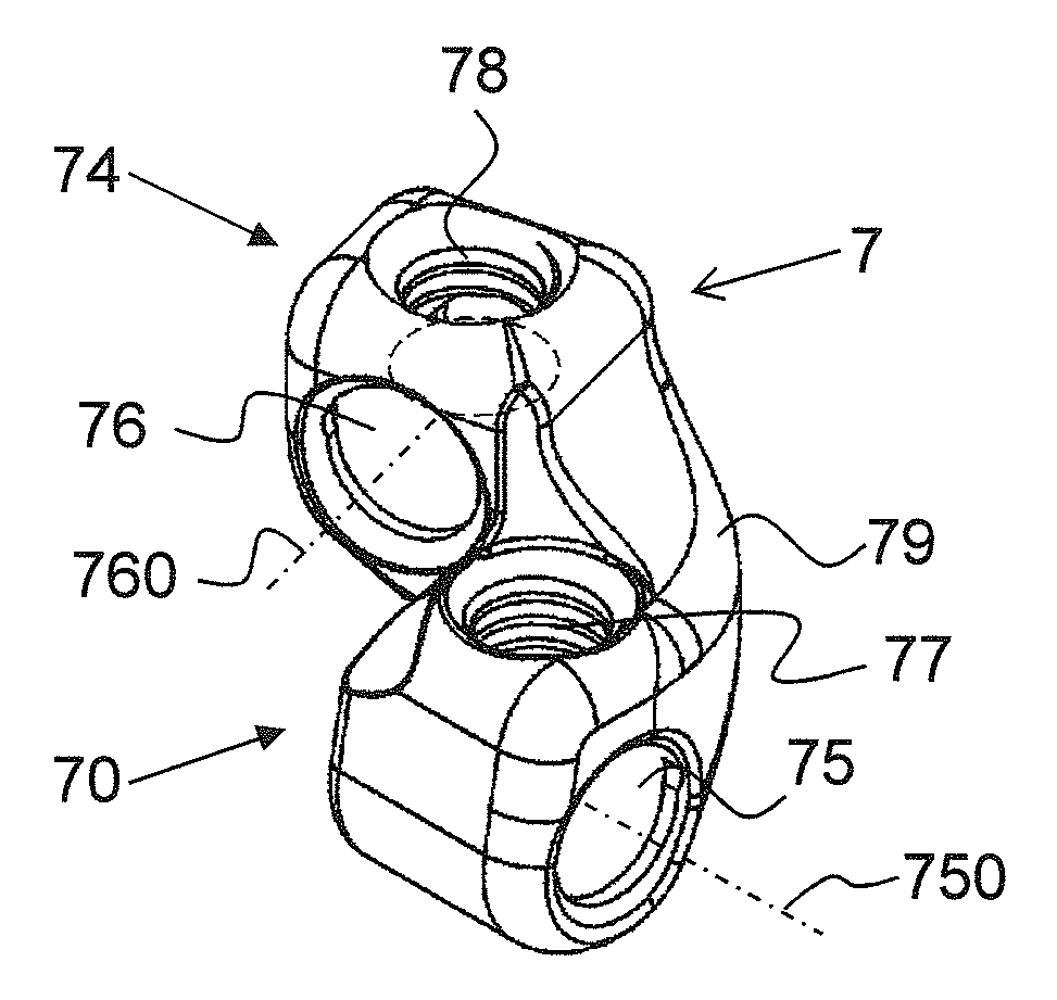
An inventive iliac connector comprises a connector head (1) and a connecting rod (2) for connecting a sacrum (S) or a spine (SP) to an ilium (I). The connector head (1) has a first hole (15) for holding a spinal rod (3) and a second hole (16) for holding the connecting rod (2), wherein the connecting rod (2) is made of a material being more flexible than titanium. This iliac connector enables a stabilization of ilium, sacrum and spine and enables at the same time movement between ilium and sacrum.

Description

[0001]This patent application claims priority of U.S. provisional application No. 61 / 644,689 filed on May 9, 2012. The present invention is in the field of stabilization and fixation of a spine.TECHNICAL FIELDPrior Art[0002]Several fixation techniques are known for the treatment of spinal deformities and pathologies, among them spinal fusion. While this is an extensive operation with potentially serious complications, a spinal fusion can be considered a lesser evil than the problem the surgeon must solve. The diseased spinal segments of a patient may be so unstable, painful and potentially nerve damaging that blocking mobile spine segments to form one bone is thought to be the best method of treatment. To fix the spine, surgeons attach one or more longitudinal fixation elements, such as rods or plates, to the spine at several fixation sites using bone screws. Often spinal bone screws are fixed through one of the most solid sections of a vertebrae, the pedicle.[0003]The vertebral ped...

Claims


Application Information

Patent Timeline
Patent Type & Authority Patents(United States)
IPC IPC(8): A61B17/70
CPCA61B17/705A61B17/7001A61B17/7031A61B17/7055A61B17/7032
Inventor LANGE, ROBERTFUNNEMARK, JAKOBFAYADA, PAULBRIGHENTI, VITTORIA
Owner LIGNE
Learn More