Pairing method, lighting device, and lighting system

a lighting device and lighting system technology, applied in the direction of connection management, instruments, light sources, etc., can solve the problems of low receiver sensitivity cost increase, and unclear state of the lighting device, and achieve the effect of less procedures and easy pairing

Active Publication Date: 2017-02-07
PANASONIC INTELLECTUAL PROPERTY MANAGEMENT CO LTD
View PDF20 Cites 0 Cited by
  • Summary
  • Abstract
  • Description
  • Claims
  • Application Information

AI Technical Summary

Benefits of technology

[0009]In addition, one aspect of the lighting device according to the present disclosure is a lighting device including: a transceiver which receives a radio command; a receiver which receives an infrared command; a storage for storing identification information of a radio remote controller serving as a master device; and a controller, wherein the controller determines whether or not the lighting device is in an initial state at power on, the initial state including a condition in which identification information of any master device is not stored in the lighting device, enters a pairing configuration mode when the controller determines that the lighting device is in the initial state, when a pairing command including identification information of the radio remote controller serving as the master device is received in the pairing configuration mode, stores the identification information of the radio remote controller serving as the master device as the identification information of the master device to the storage, and causes the lighting device to operate according to a radio command including the identification information, after storing the identification information of the master device.
[0011]With the pairing method, the lighting device, and the lighting system according to the present disclosure, it is possible to easily perform pairing with less procedure in installation work of a lighting system including a plurality of lighting devices and a radio remote controller.

Problems solved by technology

However, it is necessary to lower the receiver sensitivity of the lighting device when configuring the paring.
This involves cost increase due to inclusion of a receiver sensitivity adjuster, and an adjustment procedure for lowering the receiver sensitivity.
Furthermore, since the lighting device is turned off when configuring the paring, the state of the lighting device is unclear.

Method used


Image

  • Pairing method, lighting device, and lighting system
  • Pairing method, lighting device, and lighting system
  • Pairing method, lighting device, and lighting system

Examples


embodiment 1

[0025]The following describes a lighting system according to the present embodiment, with reference to the drawings.

[0026]1.1 A Configuration Example of a Lighting System

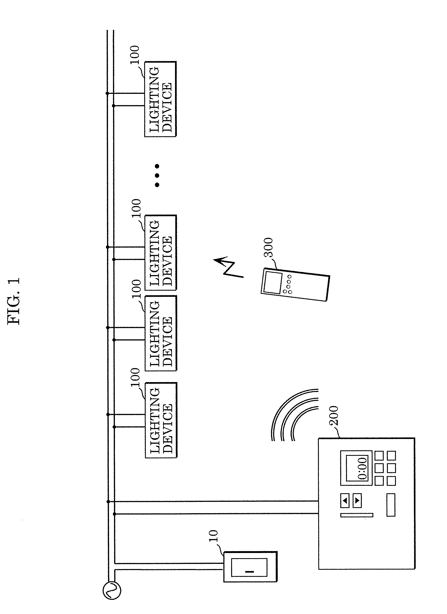
[0027]FIG. 1 is a block diagram illustrating a configuration example of a lighting system according to Embodiment 1. The lighting system illustrated in the diagram includes switch 10, a plurality of lighting devices 100; radio remote controller 200; and infrared remote controller 300.

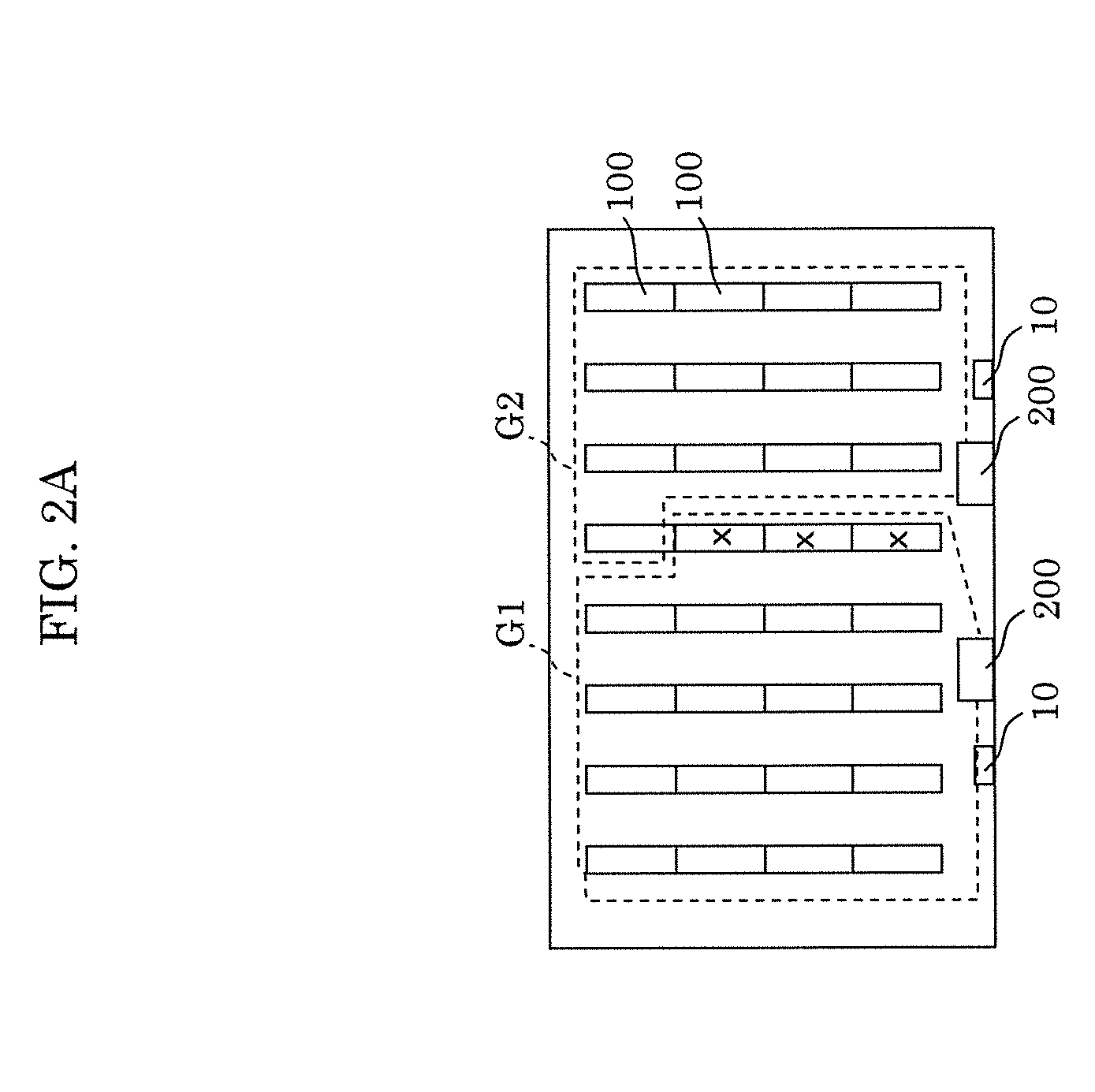
[0028]Switch 10 is, as it is called, a wall switch which switches between conduction and non-conduction of AC power lines connected to lighting devices 100. The diagram illustrates only one switch 10, and one switch 10 is provided per five lighting devices 100, for example.

[0029]Turning on and off of lighting devices 100 is controlled by switch 10, and lighting devices 100 are further controlled by a remote controller, e.g., radio remote controller 200 and infrared remote controller 300. Radio remote controller 200 and lighting devices ...

embodiment 2

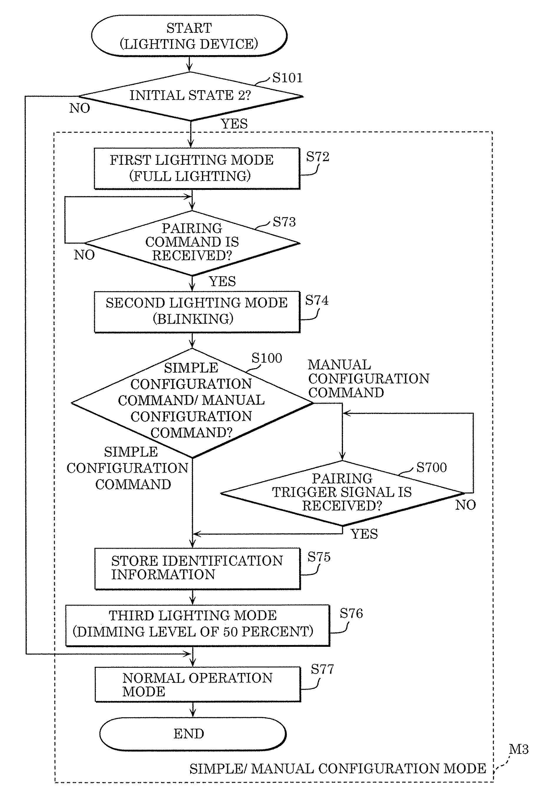
[0108]The following describes a lighting system according to Embodiment 2. In Embodiment 1, the case has been described where lighting device 100 enters the simple configuration mode when lighting device 100 is in initial state 1 at power on, and enters the manual configuration mode when lighting device 100 is in initial state 2 at power on. In contrast, the present embodiment describes a lighting system in which a pairing command is either one of a simple configuration command and a manual configuration command, and selection between the simple configuration mode and the manual configuration mode is performed based on the pairing command transmitted from radio remote controller 200.

[0109]The lighting system according to the present embodiment has a configuration substantially same as the configuration illustrated in the block diagrams of FIG. 1, FIG. 3, FIG. 4, and FIG. 5. The lighting system according to the present embodiment differs from the lighting system according to Embodime...


PUM


Abstract

A pairing method for causing lighting devices to store identification information of a radio remote controller serving as a master device is provided. The method includes: transmitting a pairing command including the identification information of the radio remote controller repeatedly on a temporary basis by the radio remote controller; determining, for each of the lighting devices, whether or not the lighting device is in an initial state in which identification information of a master device is not stored in the lighting device, at power on; storing the identification information included in the pairing command, if the paring command is received when it is determined that the lighting device is in the initial state in the determining; and causing the lighting device in which the identification information of the master device is stored to operate according to a radio command including the identification information of the master device.

Description

CROSS REFERENCE TO RELATED APPLICATION[0001]This application claims the benefit of priority of Japanese Patent Application Number 2015-081182 filed on Apr. 10, 2015, the entire content of which is hereby incorporated by reference.BACKGROUND[0002]1. Technical Field[0003]The present disclosure relates to a pairing method, in a lighting system including a plurality of lighting devices and a radio remote controller, for causing the lighting devices to store identification information of a radio remote controller serving as a master device, and to a lighting device and the lighting system.[0004]2. Description of the Related Art[0005]For example, Japanese Unexamined Patent Application Publication No. 2012-89276 discloses a lighting control device which configures pairing using (i) a plurality of lighting devices each identified by identification information (ID) and having a radio wave receiving function and (ii) a radio remote controller having a radio wave transmitting function, by sett...

Claims


Application Information

Patent Timeline
Patent Type & Authority Patents(United States)
IPC IPC(8): H05B37/02H04W76/02G08C17/02G08C23/04
CPCH05B37/0272G08C17/02G08C23/04H04W76/02H05B47/10H05B47/17H05B47/195H04W76/10
Inventor NISHIOKA, SHINSUKENANAHARA, ATSUOGOTOH, SHIGEOANDO, TAMOTSU
Owner PANASONIC INTELLECTUAL PROPERTY MANAGEMENT CO LTD
Why Eureka
Try Eureka