
Park bench

a technology for park benches and supports, which is applied in the direction of convertible stools, convertible chairs, chairs, etc., can solve the problems of troublesome assembly of planks within the supports, affecting the service life of the supports, so as to eliminate the labor and the tendency of a plank to ro

Active Publication Date: 2017-02-14
WATTON JEFFREY
View PDF13 Cites 15 Cited by
  • Summary
  • Abstract
  • Description
  • Claims
  • Application Information

AI Technical Summary

Benefits of technology

The present invention is a bench that is easy to manufacture, assemble, repair, and maintain. The individual planks are fastened to a support by a fastener that does not require drilling holes or clamping the planks in position. The planks can be easily inserted into pockets on the support without having to individually fasten them. The planks can be removed without disrupting the positioning of any other planks. The bench is modular, meaning it can be assembled in different lengths and has infinite versatility. The support has ribs and inner walls that ensure proper alignment and secure support for the planks. The invention also includes a holding pocket for easy assembly, repair, and maintenance of the planks. The color schemes and look and feel of the planks can be easily changed. The split action of the holding pocket allows for quick and efficient removal of armrests or replacement with different caps. The venting features promote durability and long-life of the products.

Problems solved by technology

This requires manufacture of several parts to secure the planks, and a great deal of time to assemble all of them onto the supports.
The fasteners are often exposed, thus potentially resulting in unwanted wear and tear or unauthorized disassembly or unwanted snagging or interference with enjoyable use of the bench.
Even so, in cases where the planks are inserted within respective pockets of a support, assembly of the planks within the supports can be troublesome where the planks, having equal lengths, cannot be individually inserted into the side pockets of the supports; rather, it is required that the ends of the several planks be simultaneously inserted into pockets of a support.
Particularly, when connecting two tubes at either end of a common hub, a user would have uncertainty as to whether one or both of the tubes was sufficiently secured within the hub or socket.

Method used


Image

  • Park bench
  • Park bench
  • Park bench

Examples


Embodiment Construction

[0030]The following detailed description is not to be taken in a limiting sense, but is made merely for the purpose of illustrating the general principles of the invention, since the scope of the invention is best defined by the appended claims.

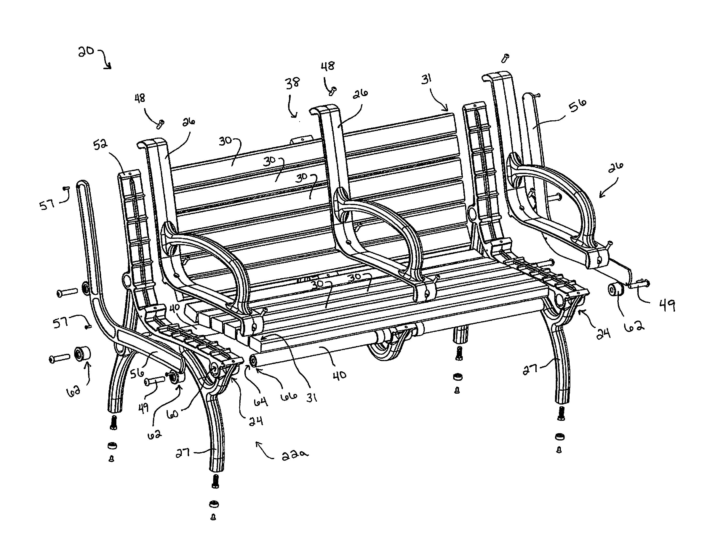
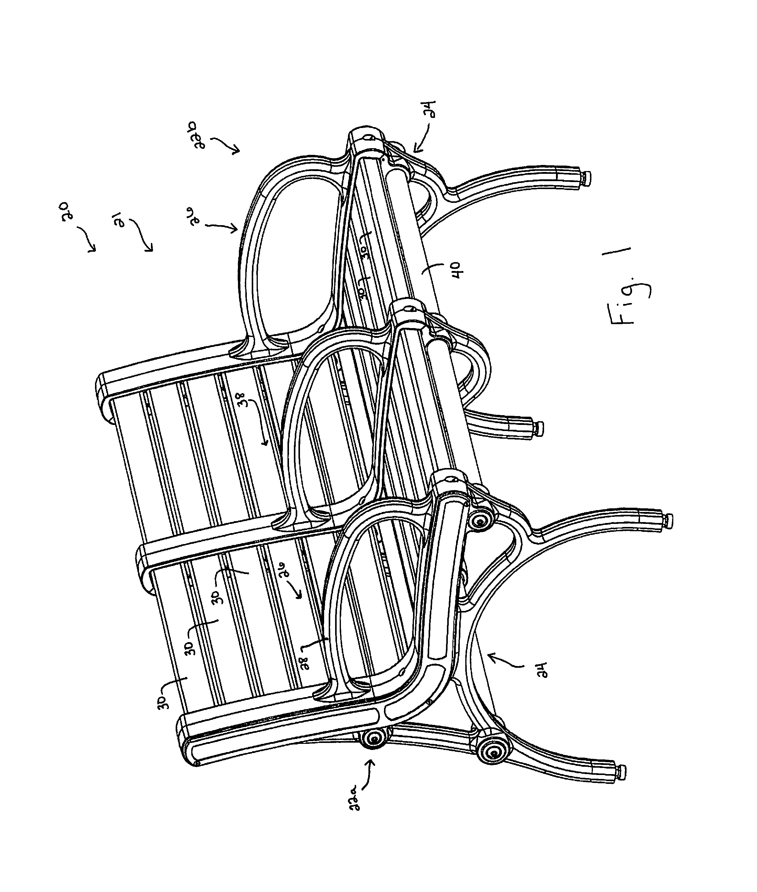
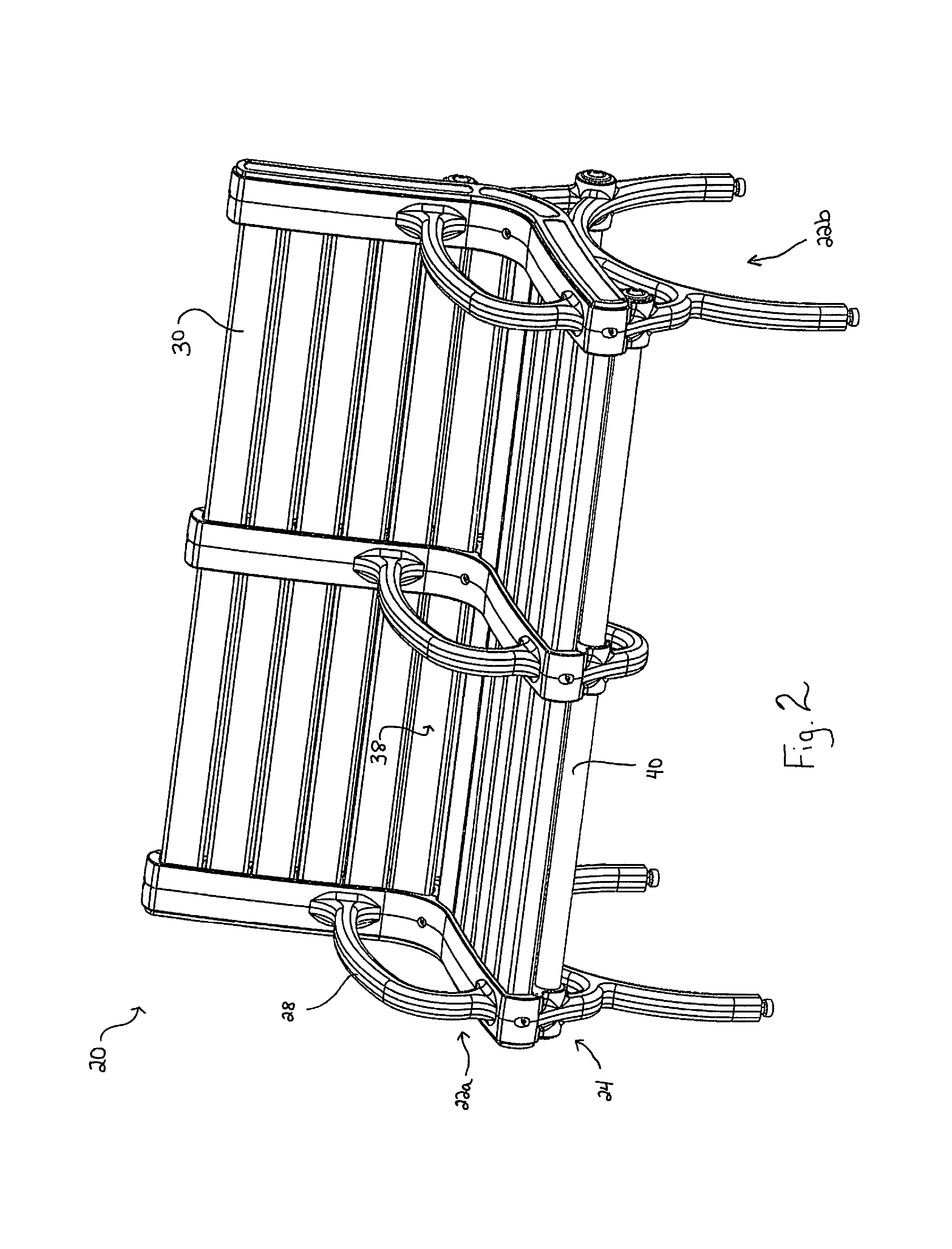
[0031]One aspect of the present invention generally provides a bench 20 depicted in FIG. 1. FIG. 2 is a reverse angle perspective view of bench 20 shown in FIG. 1. Bench 20 is preferably a sitting bench and includes support 22a and support 22b on opposite ends of bench 20. Planks 30 and tubes 40 are positioned between supports 22. Supports 22 (further described below and with respect to FIG. 3, FIG. 4 and FIG. 5) may be made of any material but are preferably made of metal and preferably are of caste aluminum (including 100% recycled U.S. aluminum). Supports 22 are preferably identical pieces and may be used interchangeably. For instance support 22a may be used as either a left-side support as shown in FIG. 1 or as a right-side support. Bench...


PUM


Abstract

A bench and frame component for holding individual planks to be used in a sitting bench where fastening an individual plank to the frame can be avoided. The frame is configured to allow a plank to be received in a holding pocket defined by an upper pocket piece and a lower pocket piece. The upper pocket piece may be connected to and removed from the lower pocket piece. The lower pocket piece may include a series of pocket segments and when connected with the upper pocket piece form a series of two-piece holding pockets for receiving a plurality of planks. The frame component is combined with other components and planks to form a bench. The bench may comprise individual bench sections that connect with similar modular sections to form a sectional bench.

Description

BACKGROUND OF THE INVENTION[0001]The present inventive concept relates generally to seating devices and benches, including park benches.[0002]Several devices are known that allow people to assume a comfortable sitting position, and benches, such as park benches, have been available over the years in many varieties. A typical bench includes a seating area and an optional backrest area. In one variety a bench typically includes a plurality of planks positioned between a pair of side supports which suspend the planks from the ground to form a seating surface. Each side of a plank is fastened or bolted to opposing supports.[0003]Another park bench is shown in the design of Messier, U.S. D498,079. In Messier the bench includes a pair of side supports receiving a plurality of planks. Messier also includes a cross bar extending between the pair of side supports and beneath the planks. The bench of Messier also includes planks that generally form a back rest of the bench. There are many oth...

Claims


Application Information

Patent Timeline
Patent Type & Authority Patents(United States)
IPC IPC(8): A47C7/02A47C7/40
CPCA47C7/405A47C7/024A47C11/00A47C13/005A47C11/005
Inventor WATTON, JEFFREY
Owner WATTON JEFFREY
Learn More