Vehicle side airbag device and manufacturing method of a side airbag
a manufacturing method and side airbag technology, applied in the direction of vehicular safety arrangments, pedestrian/occupant safety arrangements, vehicular components, etc., can solve the problems of detriment to the restraint performance in the lumbar region, and achieve excellent advantageous effect, good lumbar region restraint performance, and excellent advantageous
- Summary
- Abstract
- Description
- Claims
- Application Information
AI Technical Summary
Benefits of technology
Problems solved by technology
Method used
Image
Examples
first exemplary embodiment
[0032
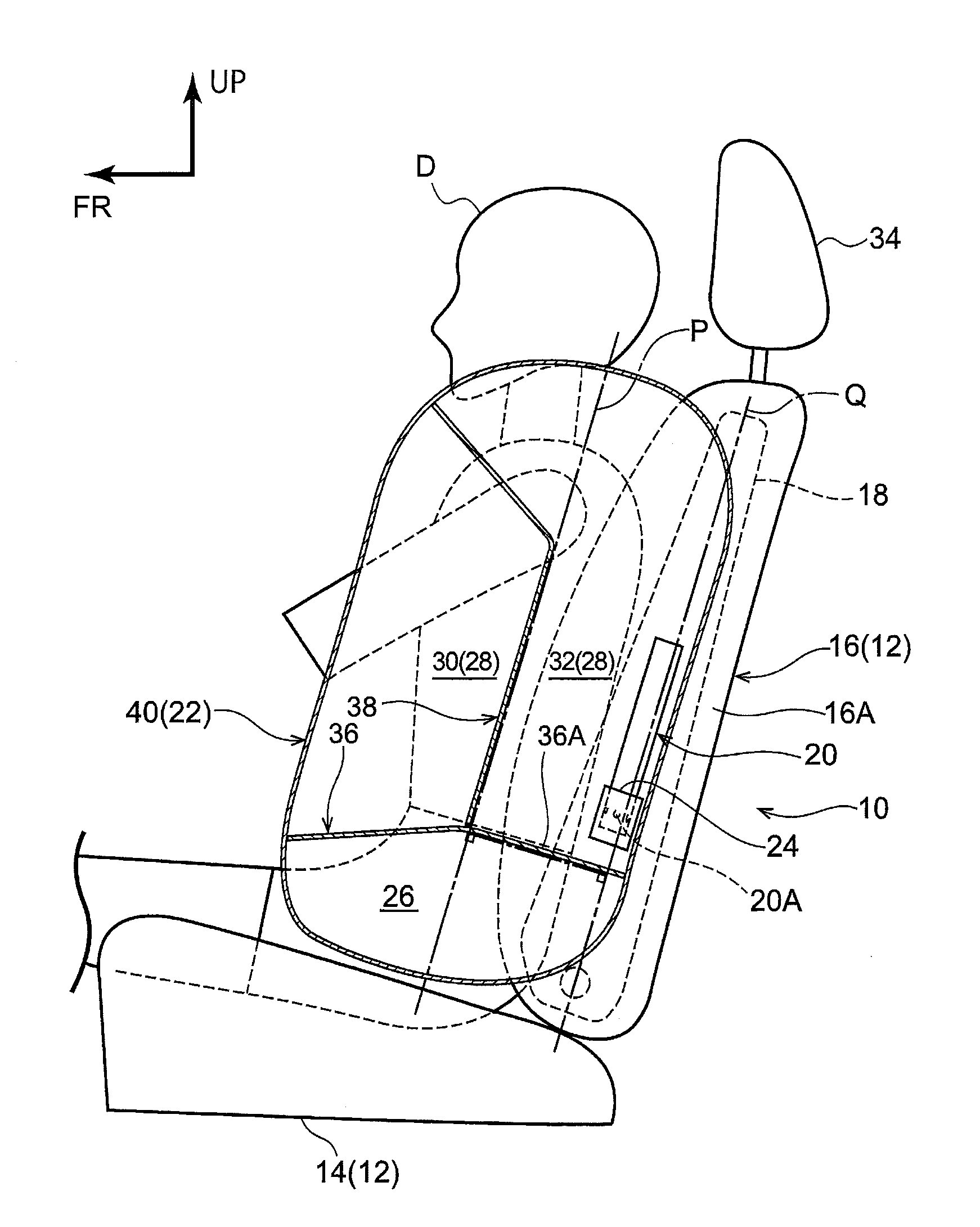
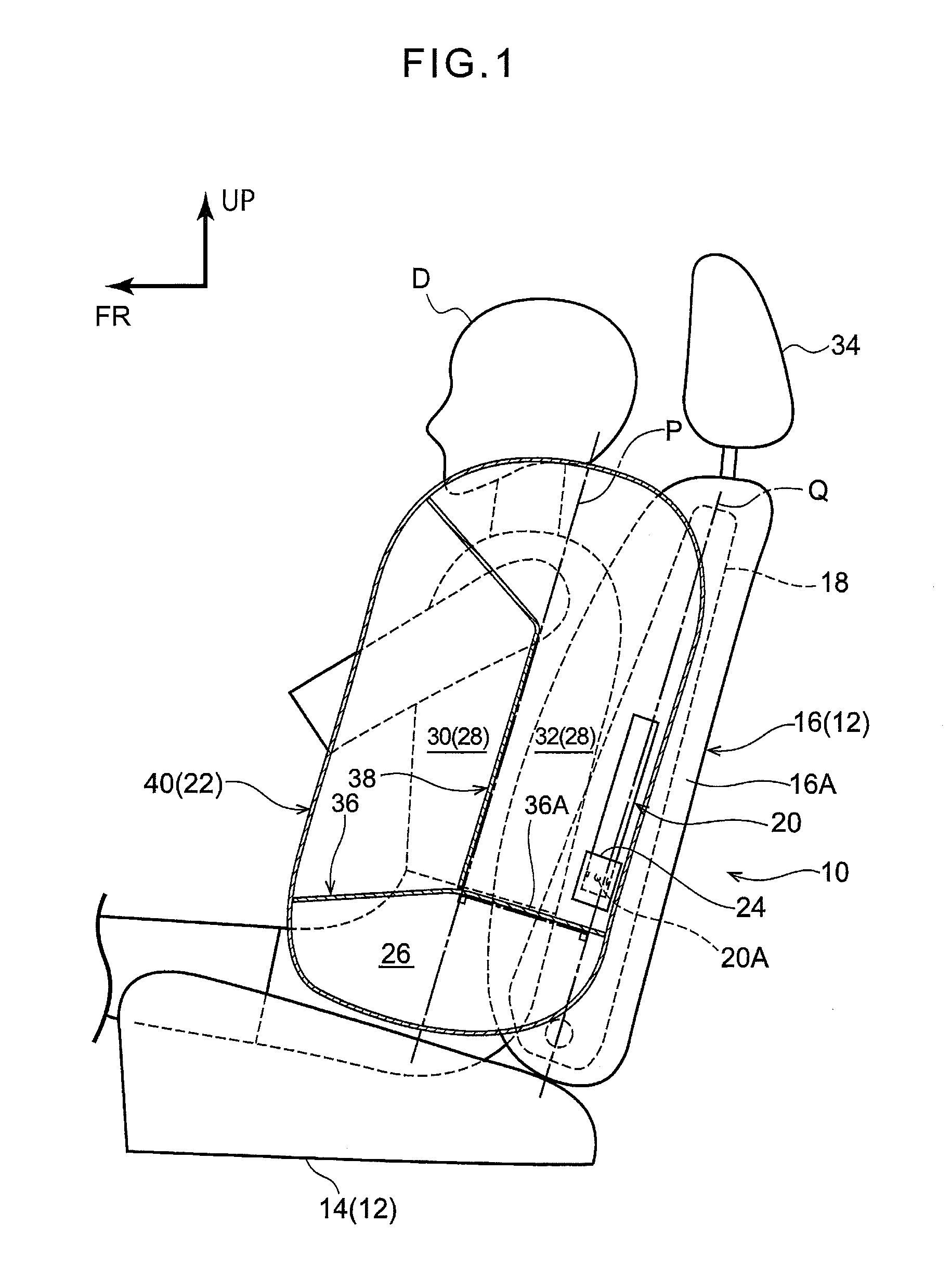
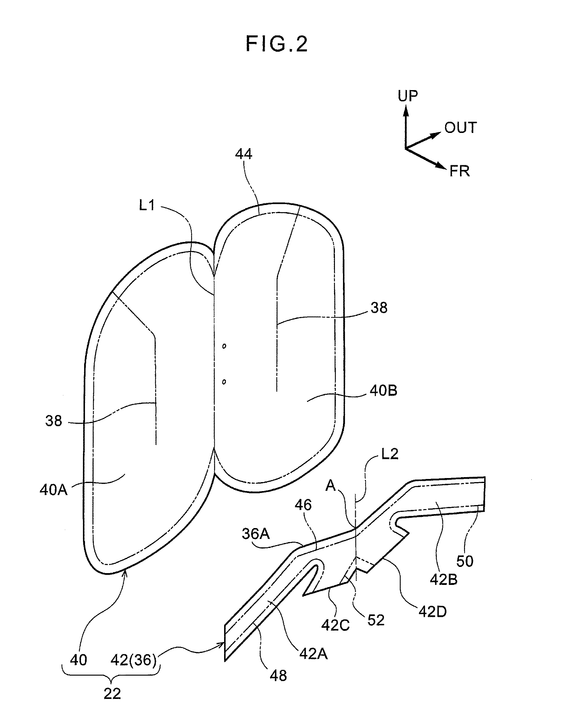
[0033]Explanation follows regarding a side airbag device according to a first exemplary embodiment of the present invention, with reference to FIG. 1 to FIG. 4. Note that in each of the drawings as appropriate, the arrow FR, the arrow UP, and the arrow OUT respectively indicate the seat front direction, the seat upper direction, and the seat width direction outside of a vehicle seat installed with the side airbag device according to the present exemplary embodiment. Unless specifically stated otherwise, simple reference to the front-rear, up-down, and left-right directions in the below explanation refers to front-rear in the seat front-rear direction, up-down in the seat up-down direction, and left-right when facing the front in the seat front-rear direction.
[0034]Overall Configuration of Side Airbag Device
[0035]As illustrated in FIG. 1, a side airbag device 10 is mounted to at least of one a side section at the vehicle width direction inside, or a side section at the vehicle w...
second exemplary embodiment
[0083
[0084]Explanation follows regarding a side airbag device according to a second exemplary embodiment of the present invention, with reference to FIG. 5.
[0085]As illustrated in FIG. 5, a side airbag 62 configuring a side airbag device 60 according to the present exemplary embodiment is configured including a side airbag main body 64, an upper-lower partitioning tether 66 configuring an upper-lower partitioning section 68, and a front-rear partitioning tether, not illustrated in the drawings, configuring a front-rear partitioning section 69. An inflator, not illustrated in the drawings, is disposed inside the side airbag 62. Note that the inflator is configured similarly to in the first exemplary embodiment.
[0086]A fold line L3 along the seat up-down direction is set at a seat width direction center portion of the side airbag main body 64. The side airbag main body 64 is folded in two at the fold line L3, superimposed in the seat width direction, and stitched together. In the pres...
third exemplary embodiment
[0092
[0093]Explanation follows regarding a side airbag device according to a third exemplary embodiment, with reference to FIG. 6.
[0094]As illustrated in FIG. 6, a side airbag 72 configuring a side airbag device 70 of the present exemplary embodiment is configured including a side airbag main body 74, an upper-lower partitioning tether 76 and an upper-lower partitioning tether 77 configuring an upper-lower partitioning section 78, a front-rear partitioning tether, not illustrated in the drawings, configuring a front-rear partitioning section 79, and a tube-shaped cloth 80 configuring a diffuser 82. An inflator, not illustrated in the drawings, is disposed inside the side airbag 72. Note that the inflator is configured similarly to in the first exemplary embodiment. The tube-shaped cloth 80 is configured so as to cover an outer periphery of the inflator, and configures a diffuser 82 for regulating the flow of gas ejected from the inflator.
[0095]A fold line L4 along the seat up-down d...
PUM
 Abstract
Description
Claims
Application Information
 - R&D
- Intellectual Property
- Life Sciences
- Materials
- Tech Scout
- Unparalleled Data Quality
- Higher Quality Content
- 60% Fewer Hallucinations
Browse by: Latest US Patents, China's latest patents, Technical Efficacy Thesaurus, Application Domain, Technology Topic, Popular Technical Reports.
© 2025 PatSnap. All rights reserved.Legal|Privacy policy|Modern Slavery Act Transparency Statement|Sitemap|About US| Contact US: help@patsnap.com


