Terminal fitting with stabilizers and connector

a technology of terminal fittings and stabilizers, which is applied in the direction of coupling contact members, coupling device connections, securing/insulating coupling contact members, etc., can solve the problems of not being able to stop the insertion of improperly oriented terminal fittings, the front end of the stabilizers may scrape off, and damage the housing, etc., to achieve the effect of a larger diameter

Active Publication Date: 2017-02-14
SUMITOMO WIRING SYST LTD
View PDF8 Cites 14 Cited by
  • Summary
  • Abstract
  • Description
  • Claims
  • Application Information

AI Technical Summary

Benefits of technology

[0008]The front end of the second stabilizer contacts the facing wall surface of the housing to stop the inserting operation of the terminal fitting if the terminal fitting is pushed into the cavity when the main body in an incorrect insertion posture. The front end of the second stabilizer is inclined to recede. Hence, there is little likelihood of damaging the facing wall surface of the housing. The front end part of the first stabilizer contacts the facing wall surface of the housing if the front end of the second stabilizer should slide on the facing wall surface of the housing. Thus, the inserting operation of the terminal fitting in the incorrect posture is stopped reliably. The front end of the first stabilizer extends steeply in the direction substantially perpendicular to the front-back direction. Therefore, the insertion of the terminal fitting is stopped with high reliability. In this case, the front end of the second stabilizer contacts the facing wall surface of the housing earlier than the first stabilizer, thereby reducing a contact force (impact force) of the first stabilizer with the housing. Thus, there is little likelihood of damaging the facing wall surface of the housing. With this configuration, an inverted insertion preventing function of the terminal fitting can be exhibited with no problem.
[0011]The invention also is directed to a connector with the above-described terminal fitting. A rear part of the cavity of the housing is formed as a rubber plug accommodating portion and has a larger diameter than a front part of the cavity. The cavity of the housing has a tapered guiding surface gradually reduced in diameter from the rear part to the front part. The front end of the stabilizer contacts the tapered guiding surface when the main body is in an incorrect insertion posture, and there is a relatively high possibility that the front end of the second stabilizer will slide on the guiding surface without stopping the inserting operation of the terminal fitting in an incorrect posture. However, the inserting operation of the terminal fitting in an incorrect posture can be stopped reliably by the contact of the front end of the first stabilizer with the guiding surface.

Problems solved by technology

However, the stabilizers contact a surface of the housing if the terminal fitting is oriented improperly to prevent complete insertion of the terminal fitting.
Front ends of the stabilizers may scrape off the facing wall surface of the housing and damage the housing if the terminal fitting is pushed forcibly into the cavity of the housing when the main body is in an incorrect insertion posture.
However, the inclined front ends of the stabilizers may slide on the facing wall surface of the housing and it may not be possible to stop the insertion of the improperly oriented terminal fitting.

Method used


Image

  • Terminal fitting with stabilizers and connector
  • Terminal fitting with stabilizers and connector
  • Terminal fitting with stabilizers and connector

Examples


Embodiment Construction

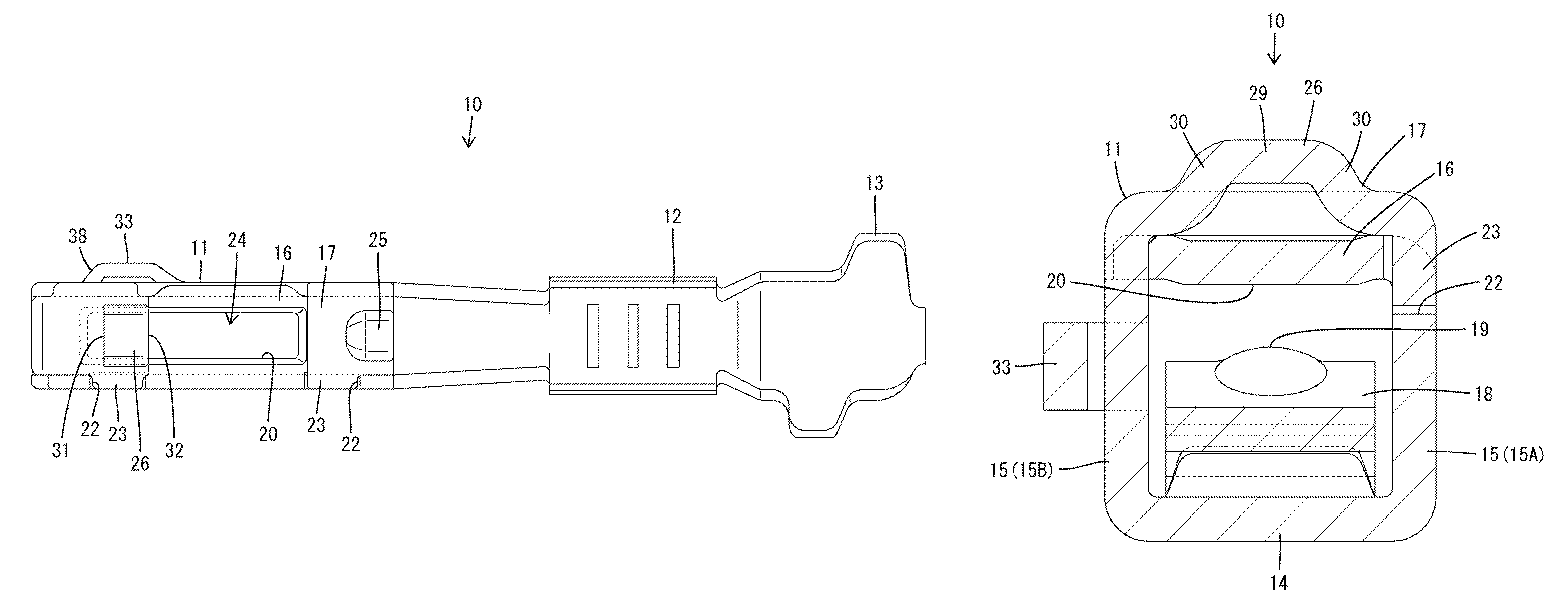
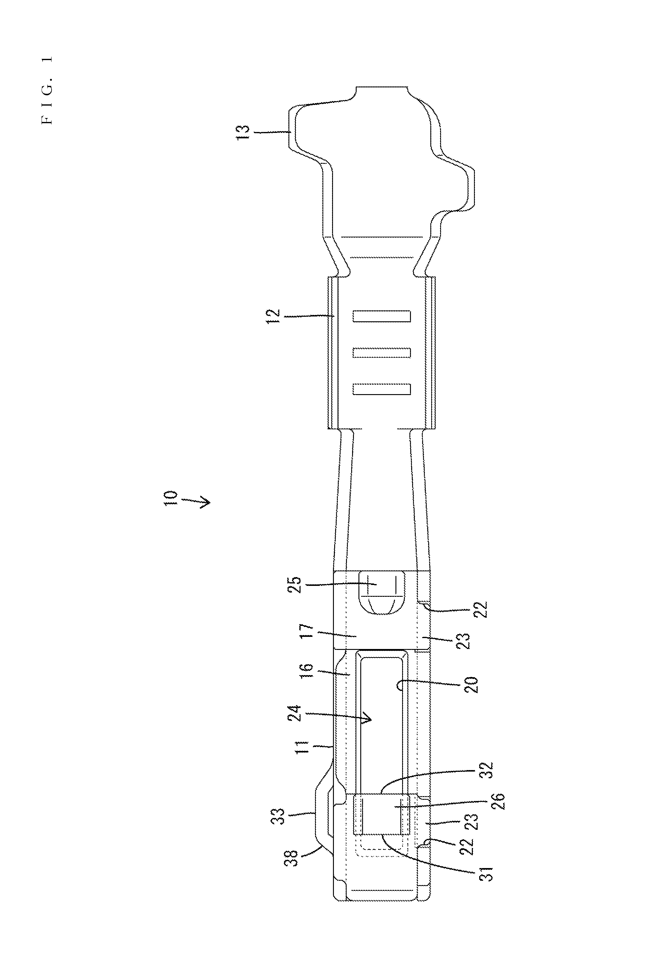
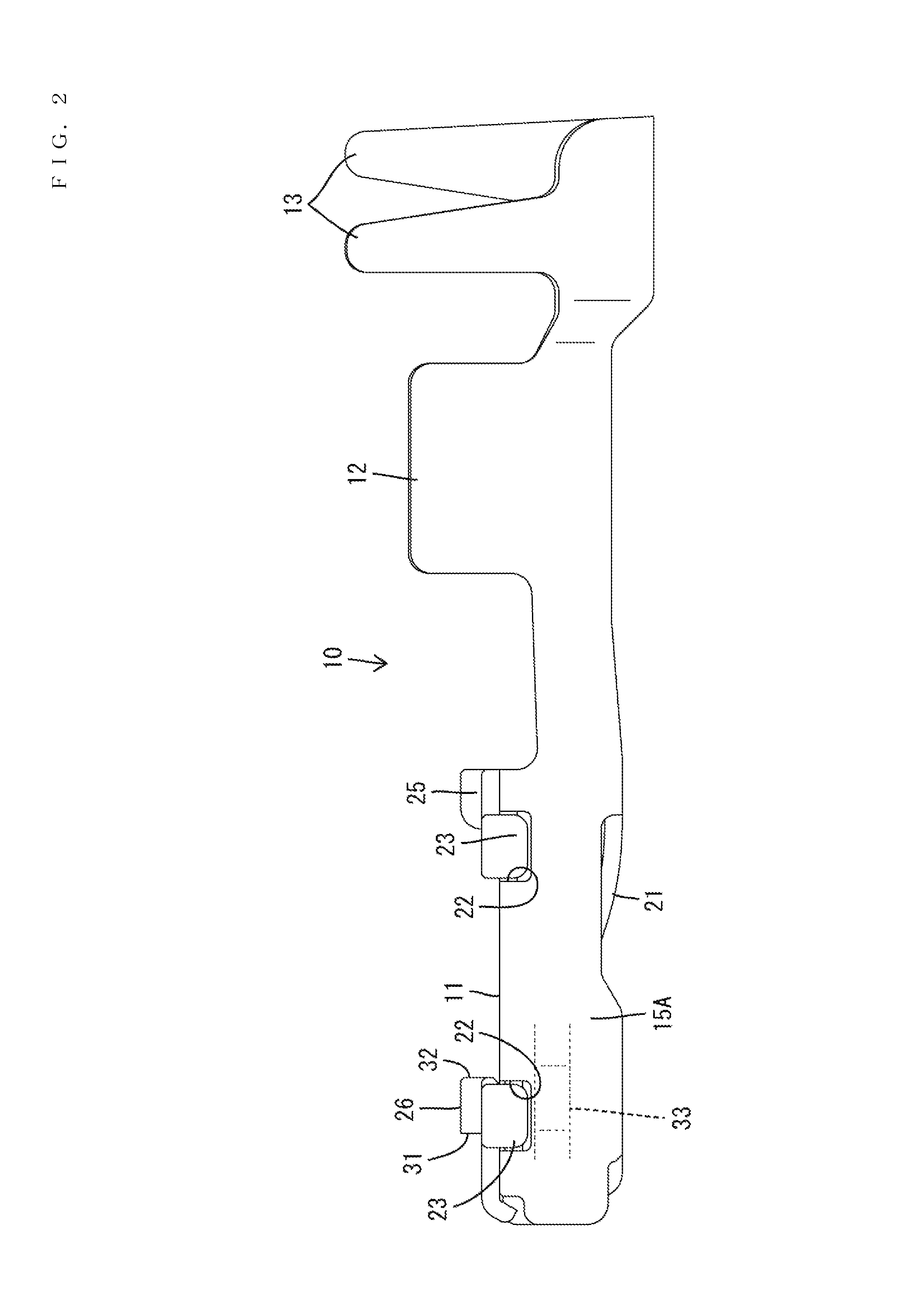
[0020]A terminal fitting 10 according to an embodiment of the invention is identified by the numeral 10 in FIGS. 1 to 8. The terminal fitting 10 is formed unitarily by bending an electrically conductive metal plate that is long and narrow in a front-back direction. The terminal fitting 10 is inserted into a cavity 61 of a connector housing 60 shown in FIG. 8 from behind (from a right side in FIG. 8) and retained and held in the cavity 61.

[0021]The housing 60 is made of synthetic resin and the cavity 61 extends therethrough in the front-back direction, as shown in FIG. 8. The cavity 61 includes a front part 62 located on a front end, a rear part 63 located on a rear end and an intermediate part 64 located between the front and rear parts 63 and 64. The rear part 63 is cross-sectionally larger than the front part 62. The front part 62 of the cavity 61 has a substantially rectangular cross-section dimensioned to receive a main body 11 of the terminal fitting 10. An unillustrated deflec...


PUM


Abstract

First and second stabilizers (26, 33) project on a main body (11) of a terminal fitting (10) while being spaced apart in a direction intersecting with a front-back direction. The first stabilizer (26) has a front end extending steeply in a direction substantially perpendicular to the front-back direction and the second stabilizer (33) has a front end part (38) inclined to recede. The front end part (38) of the second stabilizer (33) is more forward than the first stabilizer (26) so that the front end of the second stabilizer contacts a facing wall surface of a connector housing (60) before the first stabilizer (26) when an insertion posture is incorrect.

Description

BACKGROUND[0001]1. Field of the Invention[0002]The invention relates to a terminal fitting and a connector with a terminal fitting.[0003]2. Description of the Related Art[0004]U.S. Pat. No. 8,366,494 discloses a terminal fitting that is inserted into a cavity of a connector housing from behind and includes a rectangular tubular main body to be locked resiliently by a locking lance formed at an inner wall of the cavity. Two stabilizers project from the main body while being spaced apart in a front-back direction. Guiding grooves are formed in the housing and communicate with the cavity to guide an insertion of a properly oriented terminal fitting into the cavity. However, the stabilizers contact a surface of the housing if the terminal fitting is oriented improperly to prevent complete insertion of the terminal fitting. The front ends of the stabilizers have surfaces extending steeply in a direction intersecting the front-back direction.[0005]Front ends of the stabilizers may scrape ...

Claims


Application Information

Patent Timeline
Patent Type & Authority Patents(United States)
IPC IPC(8): H01R13/40H01R13/11H01R13/642
CPCH01R13/642H01R13/113
Inventor HASHIMOTO, NORIHITO
Owner SUMITOMO WIRING SYST LTD
Why Eureka
Try Eureka