
Switchable cam follower

a finger lever and cam follower technology, applied in cam followers, mechanical control devices, controlling members, etc., can solve the problems of unfavorable segmental contact region wear and high overall force relative to the section, and achieve the effect of high righting moment of the torsion leg spring and reducing wear

Active Publication Date: 2014-07-22
SCHAEFFLER TECH AG & CO KG
View PDF11 Cites 9 Cited by
  • Summary
  • Abstract
  • Description
  • Claims
  • Application Information

AI Technical Summary

Benefits of technology

The technical effect of this patent text is to reduce wear in the region where the coil assembly is attached to the bushing while maintaining a high level of protection for the torsion leg spring. This is achieved through the careful selection of the contact points on the torsion leg spring legs and the creation of an effective direction for the two contact forces. Additionally, the invention proposes a solution where the coil assembly directly extends on the axle, eliminating the need for a bushing and reducing costs. The axle is securely fixed using a radial collar that engages with a complementary groove in the axle. To decrease wear at contact points and segmental support surfaces, applied layers and hear treatment measures can be used.

Problems solved by technology

This leads to a relatively high resulting overall force in the section of the axis-offset support of the coil assembly.
This results in an undesired high wear in the segmental contact region of the coil assembly on the bushing.

Method used


Image

  • Switchable cam follower
  • Switchable cam follower
  • Switchable cam follower

Examples


Embodiment Construction

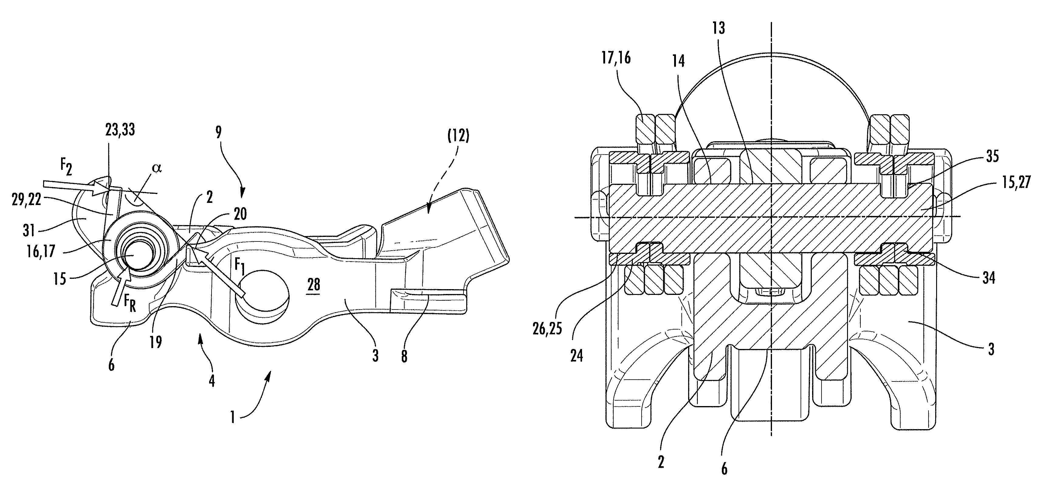
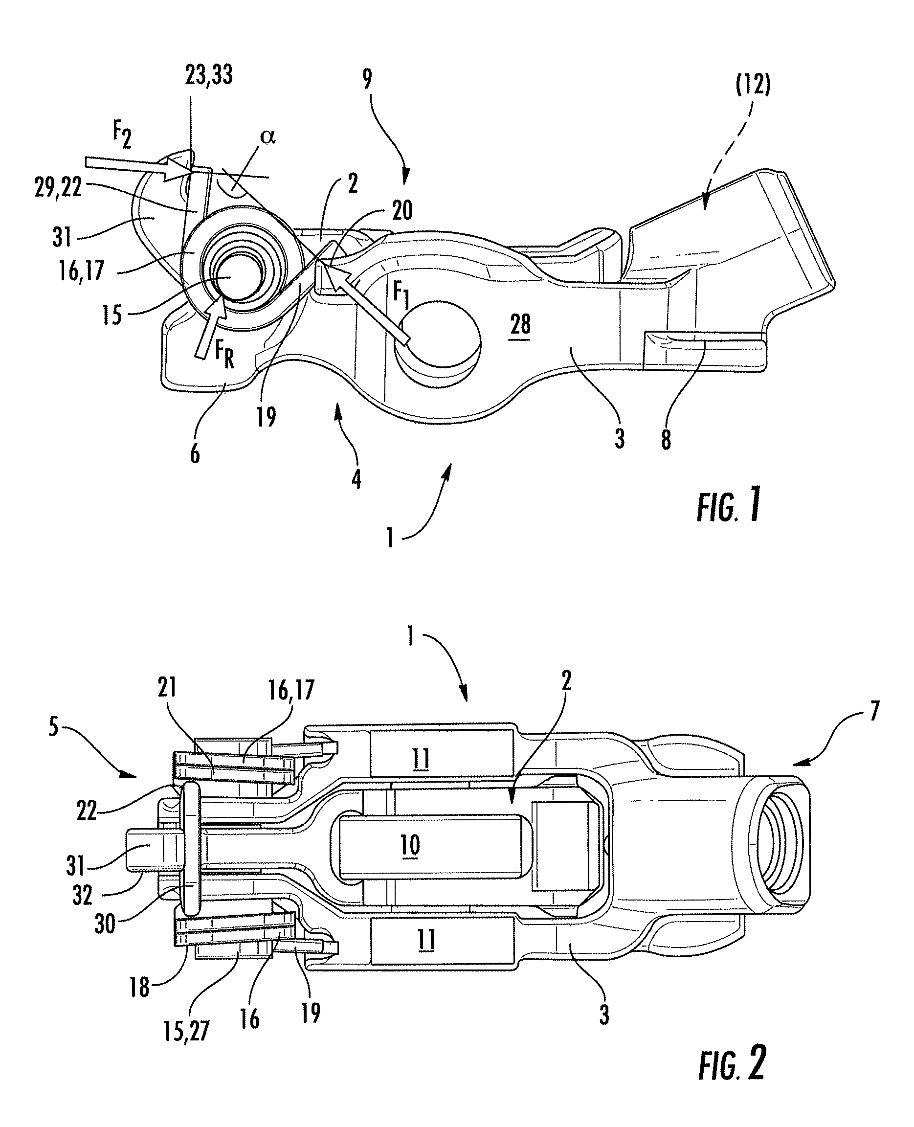
[0021]What is shown is a switchable finger lever 1 of a valve train of an internal combustion engine, said finger lever 1 comprising an elongate outer lever 3 between whose arms an inner lever 2 extends.

[0022]On one end 5 on an underside 4, the finger lever 1 comprises a support 6 for a gas exchange valve. On a further end 7, the outer lever 3 comprises on the underside 4, a complementary surface 8 for mounting on a head of a support element.

[0023]The finger lever 1 comprises on an upper side 9 of its inner lever 2, a contacting surface 10, configured in the present case as a roller, for a high lift cam. Contacting surfaces 11 for low lift cams, in contrast, are configured as sliding surfaces on the outer lever 3. In the region of the further end 7 is applied a longitudinally displaceable coupling means 12 not needing a specific description here.

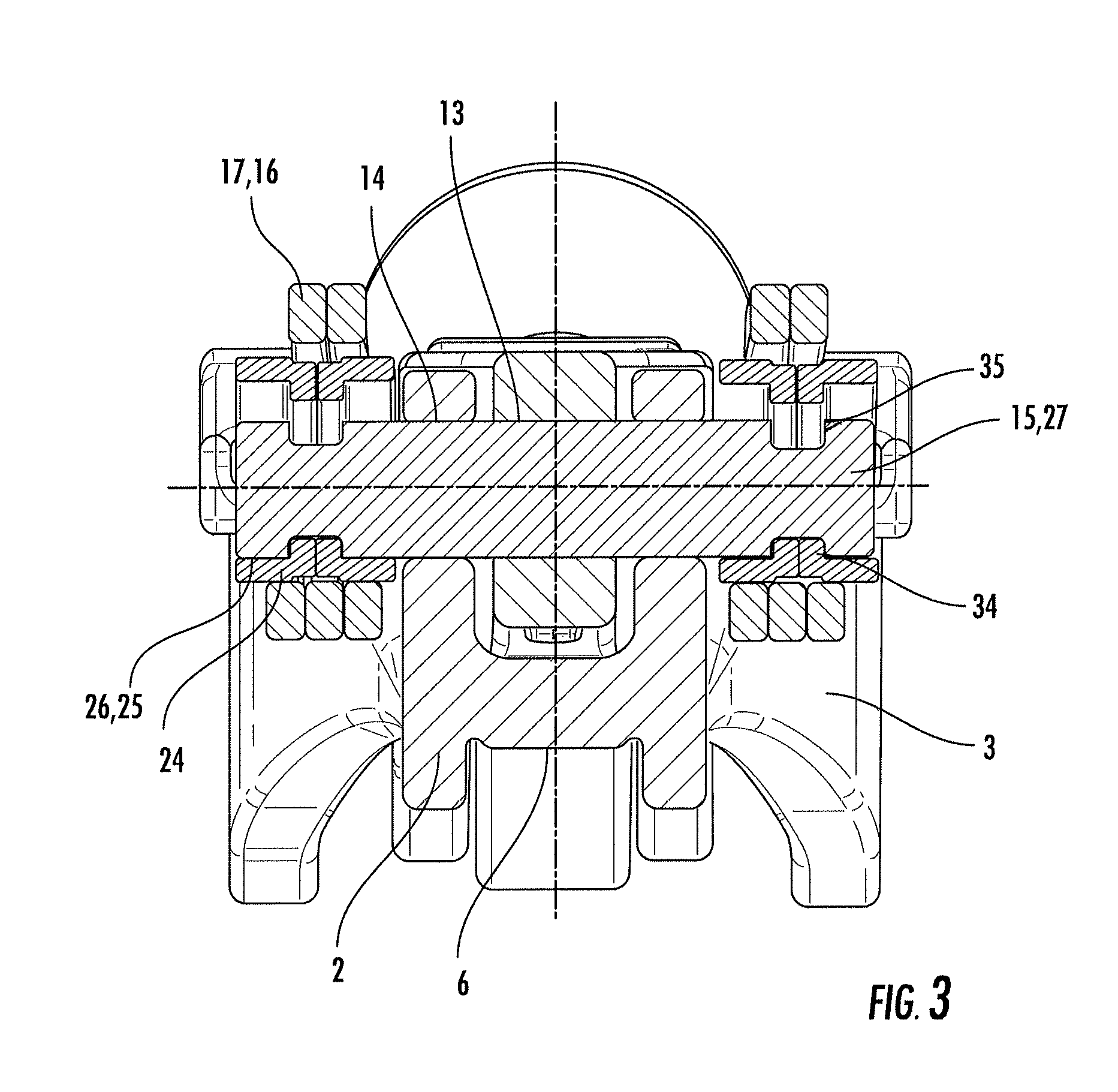
[0024]It can be seen further that the levers 2, 3 on the one end 5 extend via their bores 13, 14 on a common axle 15 towards each other and...


PUM


Abstract

A switchable cam follower (1) of a valve train of an internal combustion engine is proposed, having an inner lever and an outer lever (2, 3), wherein the levers (2, 3) can be connected to one another via coupling means (12) and run on a common pin (15) such that they can be moved pivotably relative to one another, which pin (15) is projected around by at least one group of turns (16) of a swivel pin spring (17) as cam restoring spring, wherein a first limb (19) which protrudes from an end side (18) of the group of turns (16) acts on a first clamping point (20) of the outer lever (3) and a second limb (22) which protrudes from another end side (21) of the group of turns (16) acts on a second clamping point (23) of the inner lever (2), in the rotational direction in such a way that the levers (2, 3) are present such that they are stressed towards one another, wherein the pin (15) runs in a “floating” manner with respect to the holes (13, 14), wherein the group of turns (16) comprises a bush (24) with play, wherein axial fixing of the pin (15) is produced via the offset contact of the group of turns (16) on the bush (24), which offset contact is brought about by the system stressing, and therefore the offset contact of said bush (24) on the pin (13), and wherein, in order to reduce a resulting contact force (FR) in the region of the contact of the group of turns (16) on the bush (24), the clamping points (20, 23) of the two limbs (19, 22) of the group of turns (16) are positioned in such a way that an angle (α) which is enclosed by intersecting force vectors at the clamping points (20, 23) [direction of action of the two contact forces (F1, F2)] lies in the range (90°<α<180°).

Description

FIELD OF THE INVENTION[0001]The invention concerns a switchable finger lever of a valve train of an internal combustion engine, said finger lever comprising an inner lever and an outer lever, and further comprising on an underside on one end, a support for a gas exchange valve, and also comprising on a further end, a complementary surface for a support element, one of said two levers comprising on an upper side, a contacting surface for a high lift cam, a further one of said two levers comprising a contacting surface for a low lift or zero lift cam, said two levers being able to be connected to each other through a coupling means and extending via bores on a common axle for pivoting relative to each other, said axle being surrounded by at least one coil assembly of a torsion leg spring as cam re-setting spring, a first leg protruding from one front end of said coil assembly acting on a first chucking point of the outer lever in twisting direction and a second leg protruding from a f...

Claims


Application Information

Patent Timeline
IPC IPC(8): F01L1/18
CPCF01L13/0005Y10T74/2107F01L1/181F01L1/185Y10T74/20882
Inventor GUNNEL, RONNYNITZ, NORBERT
Owner SCHAEFFLER TECH AG & CO KG
Learn More