Track-module bogie-suspension system

a bogie suspension and track module technology, applied in the field of track modules, can solve the problem that none of the prior art systems includes all elements, and achieve the effects of reducing contact forces, reducing load per axle, and high load-supporting capability

Active Publication Date: 2016-08-18
ATI TECH INC
View PDF0 Cites 10 Cited by
  • Summary
  • Abstract
  • Description
  • Claims
  • Application Information

AI Technical Summary

Benefits of technology

[0008]It is an object of this invention to provide track-module bogie-suspension apparatus which has high load-supporting capability while maintaining lower contact forces on the ground by providing lower loading per axle from more even load distribution.
[0009]Another object of this inventive track-module bogie-suspension apparatus is to minimize the unsprung mass of track-module apparatus.

Problems solved by technology

Among the challenges encountered in the use of vehicle track-module apparatus is the need to distribute the load supported by the track module among the various wheels.
However, none of these prior art systems includes all of the elements of the present invention and meets the needs as outlined above.

Method used


Image

  • Track-module bogie-suspension system
  • Track-module bogie-suspension system
  • Track-module bogie-suspension system

Examples


embodiment 10

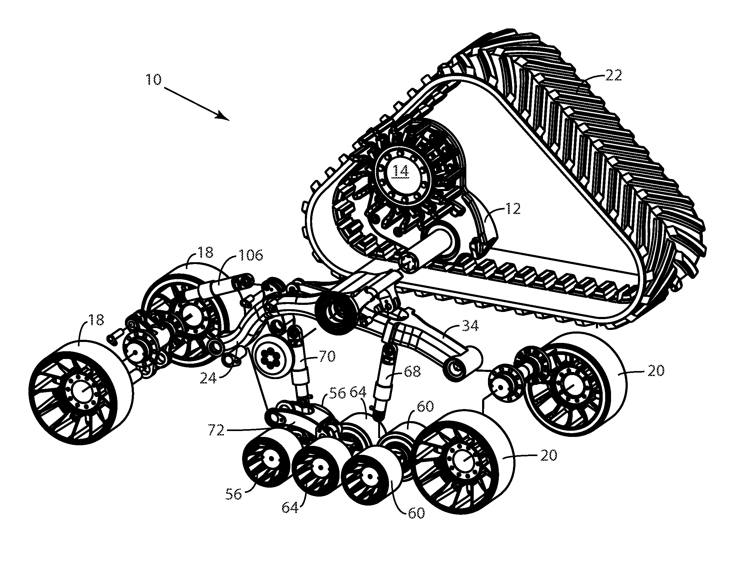
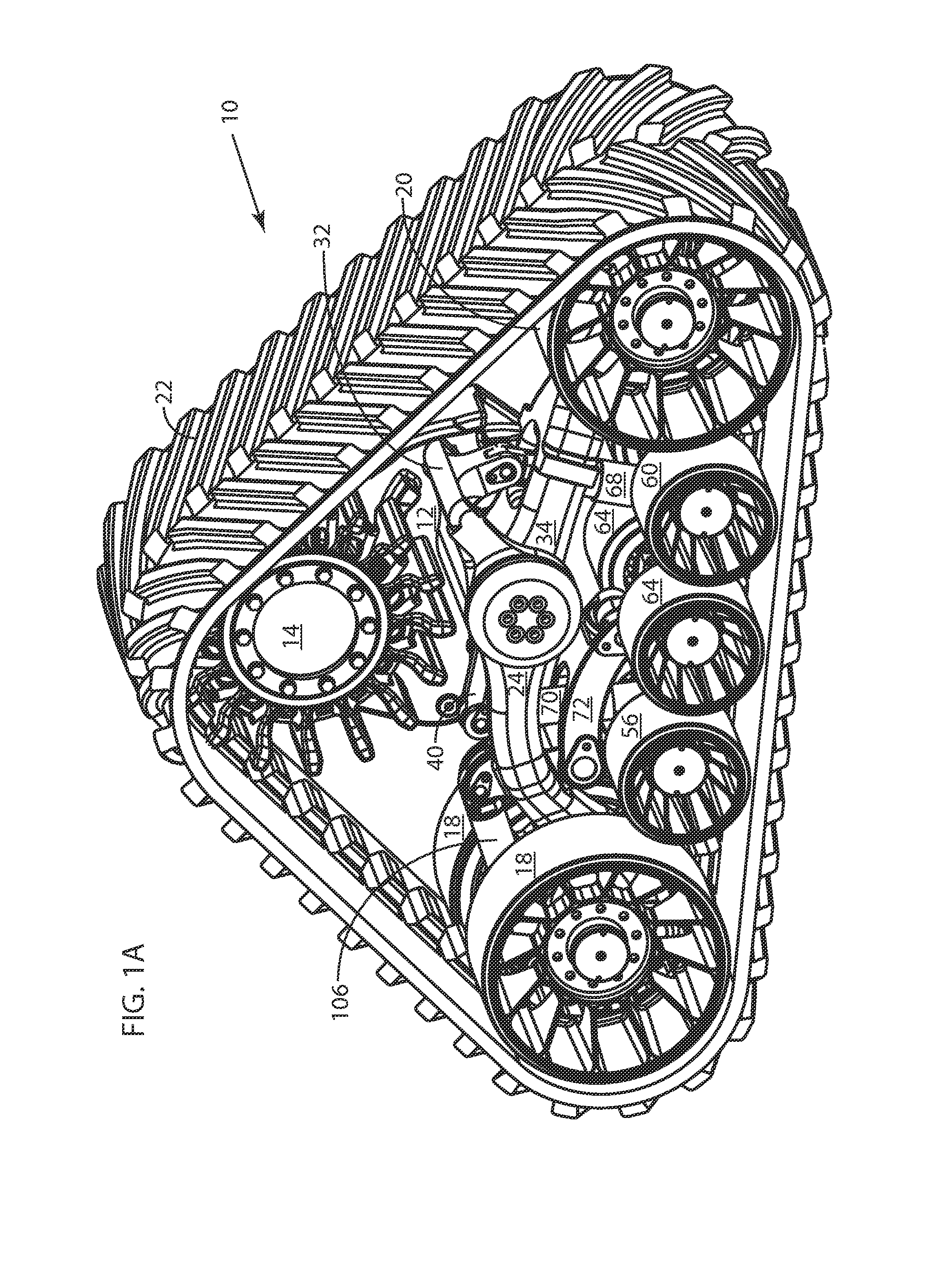
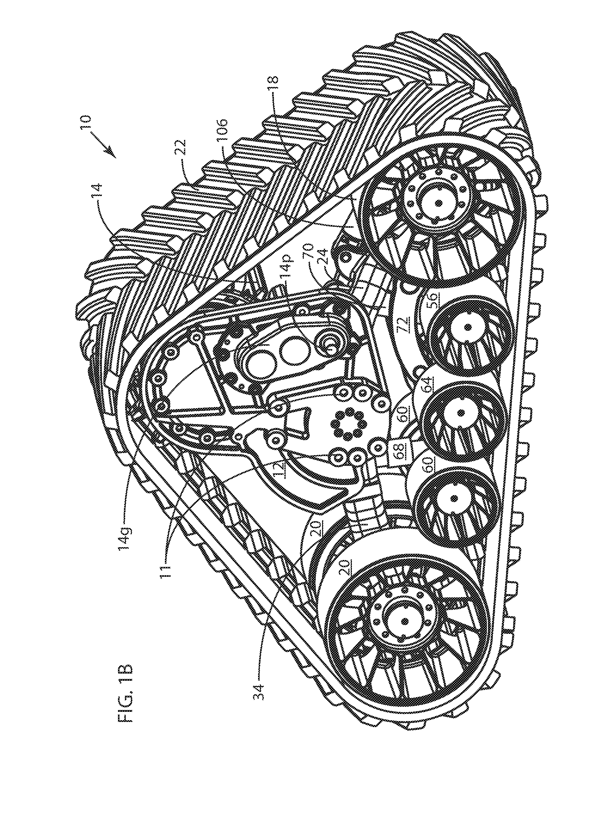
[0064]Bogie wheels 56 are leading bogie wheels, bogie wheels 60 are trailing bogie wheels, and bogie wheels 64 are middle bogie wheels. Bogie wheels 56, 60 and 64 are part of a bogie assembly 46. Embodiment 10 also includes a leading suspension arm 24, a trailing suspension arm 34, a leading suspension element 68, a trailing suspension element 70, and a tensioning element 106. Leading suspension element 68 includes upper end 68U and a lower end 68L, and trailing suspension element 70 includes an upper end 70U and a lower end 70L. The upper-end and lower-end nomenclature and reference number usage is specifically shown in FIGS. 4 and 18-19 and discussed with respect to the embodiment of FIGS. 18-19.

[0065]The direction of forward travel of the track module of embodiment 10 (and other similar embodiments presented herein) is defined by leading idler wheels 18 being ahead of trailing idler wheels 20. FIG. 4 includes an arrow 122 indicating the direction of travel applicable to all embod...

embodiment 200

[0107]Track-module embodiment 200 differs from all of the previously-described embodiments of track-module apparatus in that movements of leading suspension element upper end 68U at first suspension joint 82p and trailing suspension element upper end 70U at second suspension joint 86p are interdependent. Such interdependence is brought about by track-module apparatus 200 including unitary leading and trailing idler arms 202 (unitary structure 202). The unitary character of such arm structure is indicated by reference number 202 on both leading and trailing portions of unitary structure 202. As best seen in FIG. 18, the leading and trailing portions of the unitary structure 202 are rigidly connected to form a single structure with leading and trailing portions rotatably attached to frame 12 at suspension-arm axis 44. Since first suspension joint 82p and second suspension joint 86p are on opposite sides of unitary structure 202 with respect to suspension arm axis 44, upward movement o...


PUM


Abstract

Track-module bogie-suspension apparatus for attachment to a track module having a frame, a drive wheel and an endless track. The bogie-suspension apparatus comprises (a) a bogie assembly having a bogie mount, at least one rotatable ground-engaging bogie wheel thereon, and forward and rearward bogie-mount connections; (b) first and second load- and ground-responsive suspension joints spaced from one another in a forward / rearward direction; and (c) leading and trailing suspension elements each having an upper end and a lower end, the upper ends of the leading and trailing suspension elements rotatably attached to the first and second suspension joints, respectively, and the lower ends thereof rotatably attached to the rearward and forward bogie-mount connections, respectively.

Description

RELATED APPLICATIONS[0001]This application is a continuation-in-part of application Ser. No. 14 / 625,229 filed on Feb. 18, 2015, the contents of which are incorporated herein by reference.FIELD OF THE INVENTION[0002]The invention relates generally to the field of vehicle track-module systems of the type typically for use in place of vehicle wheels and, more particularly, to track modules having leading and trailing wheels and at least one load-supporting bogie wheel between the leading and trailing wheels, all of which are engaged by an endless track extending around the wheels to drive a vehicle along the ground.BACKGROUND OF THE INVENTION[0003]Agricultural vehicles such as tractors, combines and the like are commonly used in agricultural fields for a variety of jobs, and construction vehicles and other large work vehicles are used for many different jobs on a variety of ground surfaces. Typically, these vehicles have large wheels with tires on which the vehicles are supported on th...

Claims


Application Information

Patent Timeline
Patent Type & Authority Applications(United States)
IPC IPC(8): B62D55/104B62D55/10B60G5/01B62D55/14B60G11/27B62D55/112B62D55/084
CPCB62D55/104B62D55/112B62D55/10B62D55/0842B62D55/14B62D55/30B60G5/01B60G2202/15B62D55/108B62D55/1083B62D55/1086B60G11/27B62D55/305B62D55/1125
Inventor TIEDE, DUANERESHAD, JAMSHEEDSTACY, TIMOTHY D.JUNCKER, KENNETH J.
Owner ATI TECH INC
Why Eureka
Try Eureka