Noncontact measuring device

a technology of electronic wheel gauges and measuring devices, which is applied in the direction of image enhancement, instruments, image data processing, etc., can solve the problems of easy human error in the use of the device, limited human perceptual capabilities, and a bit of bulky

Active Publication Date: 2017-02-14
INT ELECTRONICS MACHINES
View PDF13 Cites 26 Cited by
  • Summary
  • Abstract
  • Description
  • Claims
  • Application Information

AI Technical Summary

Benefits of technology

[0011]Other aspects of the invention provide methods, systems, program products, and methods of using and generating each, which include and / or implement some or all of the actions described herein. The illustrative aspects of the invention are designed to solve one or more of the problems herein described and / or one or more other problems not discussed.

Problems solved by technology

Such devices are inexpensive and simple, however, use of the device is prone to human error based on precise placement and angle of view of the devices.
Furthermore, an overall accuracy is limited by human perceptual capabilities.
These devices provide more accurate measurements, but are somewhat bulky and are often difficult to fit into restricted spaces afforded by transit railcar wheels.
The device includes moving components, which are subject to wear and breakage and often cannot fit in small areas.
These measurement systems have been shown to be highly effective and reliable at measuring railroad wheels from structured light projections, but are extremely expensive, permanent installations.
However, this gauge cannot measure diameter without the use of a large, separate fixture and a separate measurement.
Furthermore, the gauge requires the operator to move the sensor head in a precise manner, requires a significant standoff distance, and requires a separate connected computational and display component.
As a result, the gauge also requires use of an expensive and sophisticated inertial measurement unit (IMU) to recognize and compensate for significant variations of poses of the operator's hand while taking the measurements.

Method used


Image

  • Noncontact measuring device
  • Noncontact measuring device
  • Noncontact measuring device

Examples


Embodiment Construction

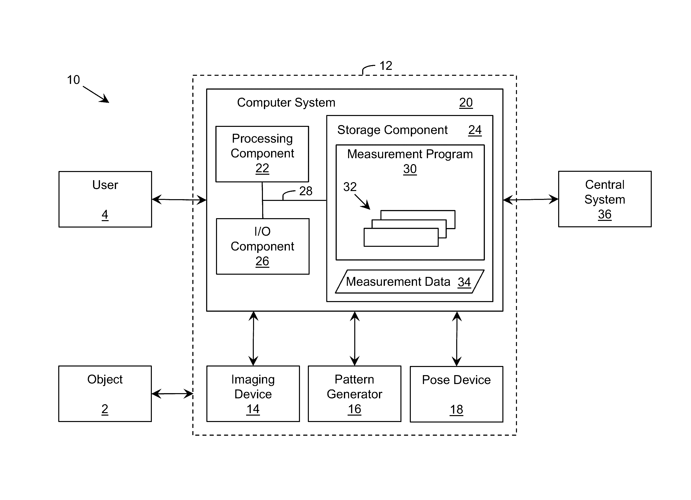
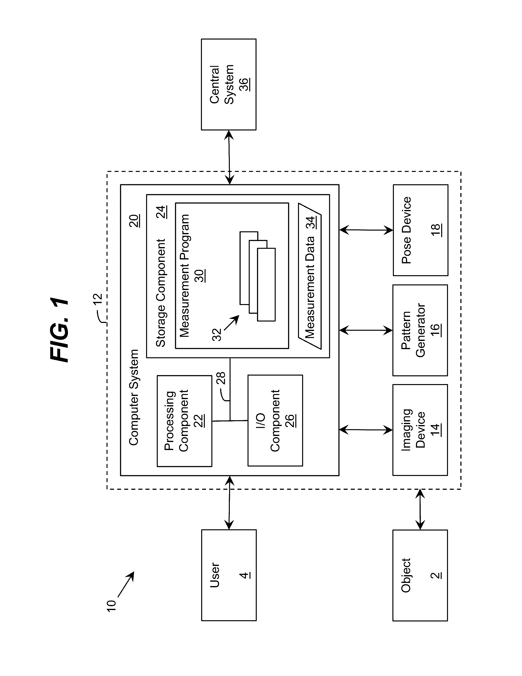
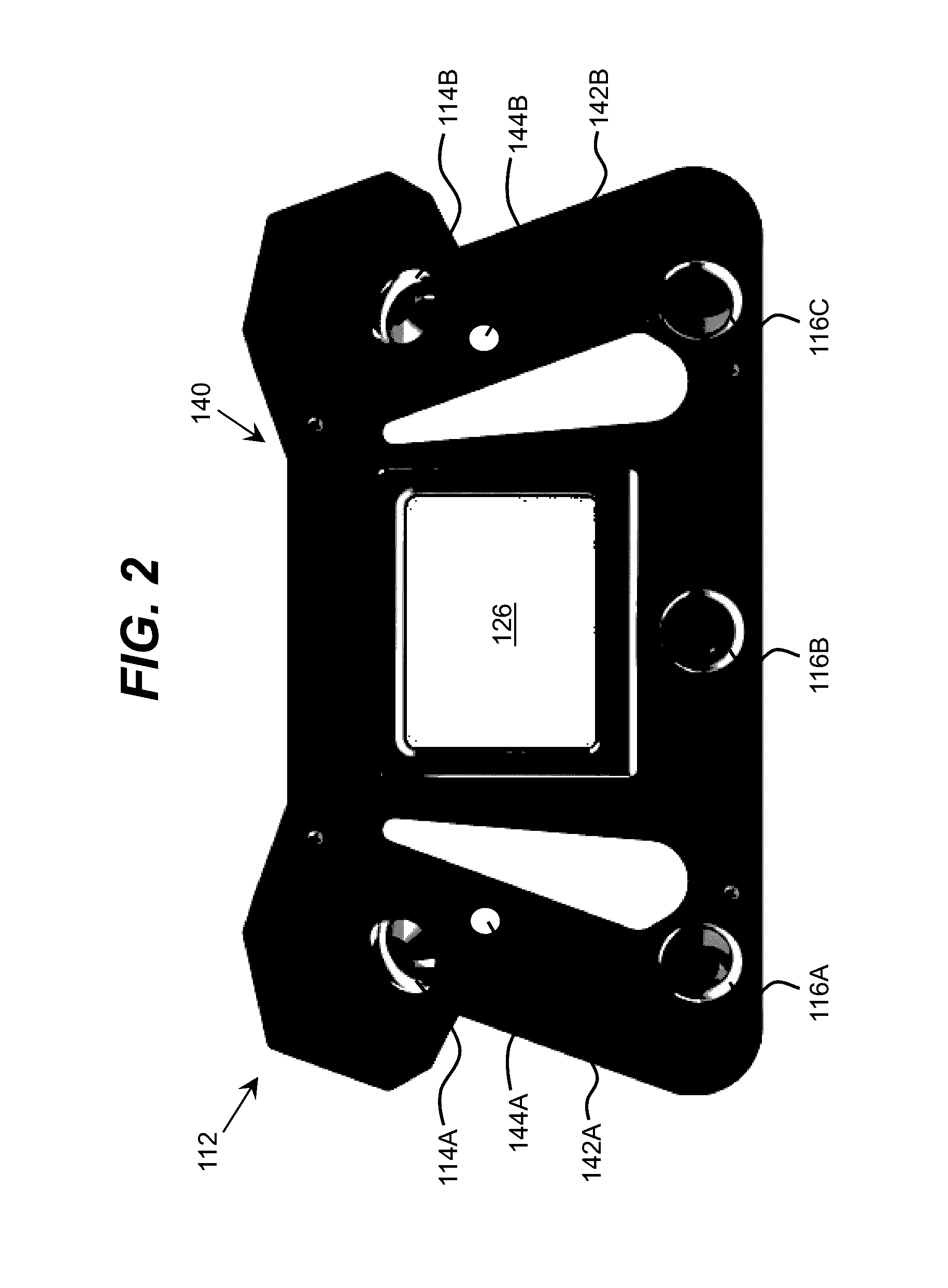
[0022]As indicated above, aspects of the invention provide a solution including a noncontact electronic measurement device. The measurement device includes one or more imaging devices configured to acquire image data of a surface of an object located in a measurement region relative to the measurement device and one or more projected pattern generators configured to generate divergent pattern(s) of structured light, which impact the surface of the object within a field of view of the imaging device when the object is located in the measurement region. Using image data acquired by the imaging device(s), a computer system can measure a set of attributes of the surface of the object and / or automatically determine whether the measurement device is within the measurement region. An embodiment of the measurement device is configured to be held by a human user during operation. As used herein, unless otherwise noted, the term “set” means one or more (i.e., at least one) and the phrase “any...


PUM


Abstract

A solution including a noncontact electronic measurement device is provided. The measurement device includes one or more imaging devices configured to acquire image data of a surface of an object located in a measurement region relative to the measurement device and one or more projected pattern generators configured to generate divergent pattern(s) of structured light, which impact the surface of the object within a field of view of the imaging device when the object is located in the measurement region. Using image data acquired by the imaging device(s), a computer system can measure a set of attributes of the surface of the object and / or automatically determine whether the measurement device is within the measurement region. An embodiment is configured to be held by a human user during operation.

Description

REFERENCE TO RELATED APPLICATIONS[0001]The current application claims the benefit of co-pending U.S. Provisional Application No. 61 / 852,768, titled “Noncontact Electronic Wheel Gauge,” which was filed on 21 Mar. 2013, and which is hereby incorporated by reference.GOVERNMENT LICENSE RIGHTS[0002]This invention was made with partial government support under contract no. TRANSIT-72 awarded by the National Academy of Sciences. The government has certain rights in the invention.TECHNICAL FIELD[0003]The disclosure relates generally to measuring aspects of railroad wheels, and more particularly, to a noncontact electronic wheel gauge.BACKGROUND ART[0004]Current systems for measuring aspects of railroad wheels include numerous types of physical gauges, such as a “J” type steel wheel gauge approved by the Association of American Railroads (AAR) and a “pi tape” for measuring a circumference / diameter of railroad wheels. Such devices are inexpensive and simple, however, use of the device is pron...

Claims


Application Information

Patent Timeline
Patent Type & Authority Patents(United States)
IPC IPC(8): H04N7/18G01B11/25G01B5/08
CPCH04N7/18G01B11/25G01B11/2545H04N23/90G06T7/70B61K9/12G01M17/10G06T7/001G06T7/60G06T2207/30244
Inventor MIAN, ZAHID F.SPOOR, RYK E.GAMACHE, RONALD W.
Owner INT ELECTRONICS MACHINES
Why Eureka
Try Eureka