Scaffold with scaffolding elements and methods for erection thereof

a technology of scaffolding and scaffolding elements, which is applied in the field of scaffolding elements and methods for erection thereof, can solve the problems of affecting the loss of a large amount of time in the erection of particularly large scaffolds, and the inability to perform the task for a limited period of time, so as to increase the stability of the scaffold

Active Publication Date: 2017-02-28
KEERSMAEKERS MARC
View PDF54 Cites 0 Cited by
  • Summary
  • Abstract
  • Description
  • Claims
  • Application Information

AI Technical Summary

Benefits of technology

[0016]The above stated applications also specify a guide system for a carrier unit or lift unit adapted to be mounted on the ledgers of the scaffold and adapted for coupling to the displacing means (e.g. wheel mechanisms) of a carrier unit or lift unit. They describe lifts which can be provided with displacing means. The displacing means can comprise a number of (for instance four) wheel mechanisms which can optionally be driven and which are adapted to move (for instance travel) on a rail system which can be arranged through the scaffolding construction at a determined ledger level (for instance ground level). This lift unit can in this way be readily displaced through the whole scaffolding construction via the determined level (for instance ground level), particularly to adjacent scaffold columns. This rail system preferably comprises at least two rails which are adapted for mounting on the ledgers of the scaffold, and which are on the other hand adapted for coupling to the displacing means of the lift unit (for instance to wheels of the wheel mechanisms of the lift unit).
[0033]In embodiments of the present invention a scaffold is described wherein these rods, when the rails are mounted horizontally in appropriate manner in the scaffold, comprise two diagonally opposite longitudinal ribs running in the same vertical plane. The other two ribs are then situated in the same horizontal plane. In this case the use of a spacer is not necessary between the rods and the rest of the ledgers or support blocks. Production is easier and allows the use of simple and efficient locking mechanisms, which can be used to secure a displaceable platform against release. Such a mechanism can for instance engage under the edge of the two ribs in the same horizontal plane.
[0050]According to embodiments of the present invention the mobile platform preferably comprises a number of wheel devices, for instance four, six or eight wheels. Two, three or four aligned wheel devices can for instance be present on each of the sides in the longitudinal direction of the mobile platform. In determined embodiments of the present invention these wheel devices can be retracted and extended in a direction substantially perpendicular to the longitudinal direction of the mobile platform typically corresponding to the longitudinal direction of the scaffold. This can in specific cases simplify the installation, storage or passage of the platform.
[0083]In embodiments of the present invention a support means is described in which each threaded rod element is provided with a corresponding nut, and further comprising a removable blocking means which prevents undesired release of the nut from the threaded rod element.
[0087]In embodiments of the present invention a stabilizing element for use in a scaffold is described which is adapted to be able to orient the arms such that they come to lie substantially parallel, wherein their first outer ends and their second outer ends coincide. The two or four arms or rods can thus be folded together so that they become shorter and can still be stocked horizontally.
[0092]In embodiments of the present invention a scaffold is described comprising at least one scaffold section and at least one stabilizing element as described above, wherein each of the second outer ends of the arms of the stabilizing element is secured close to one of the four corners of the front plane of a scaffold section formed by the two uprights and two lengthwise ledgers defining the plane. The use of such diagonals allows the stability of the scaffold to be increased, and the diagonals can be stocked horizontally.

Problems solved by technology

It is known that erection and dismantling of a scaffold is very labour-intensive.
This means that a relatively large amount of time is lost in the erection of particularly larger scaffolds.
The physical load for people erecting the scaffold is further a heavy one, so that many people can only perform this task for a limited part of their life.

Method used


Image

  • Scaffold with scaffolding elements and methods for erection thereof
  • Scaffold with scaffolding elements and methods for erection thereof
  • Scaffold with scaffolding elements and methods for erection thereof

Examples


Embodiment Construction

[0110]The above stated and other advantageous features and objects of the invention will become more apparent and the invention better understood from the following detailed description when read in combination with the respective drawings.

[0111]The description of the aspects of the present invention is given by means of specific embodiments and with reference to, but not limited to, specific drawings. The figures shown are only schematic and should be deemed as non-limitative. Determined elements or features may for instance be shown out of proportion or scale in relation to other elements.

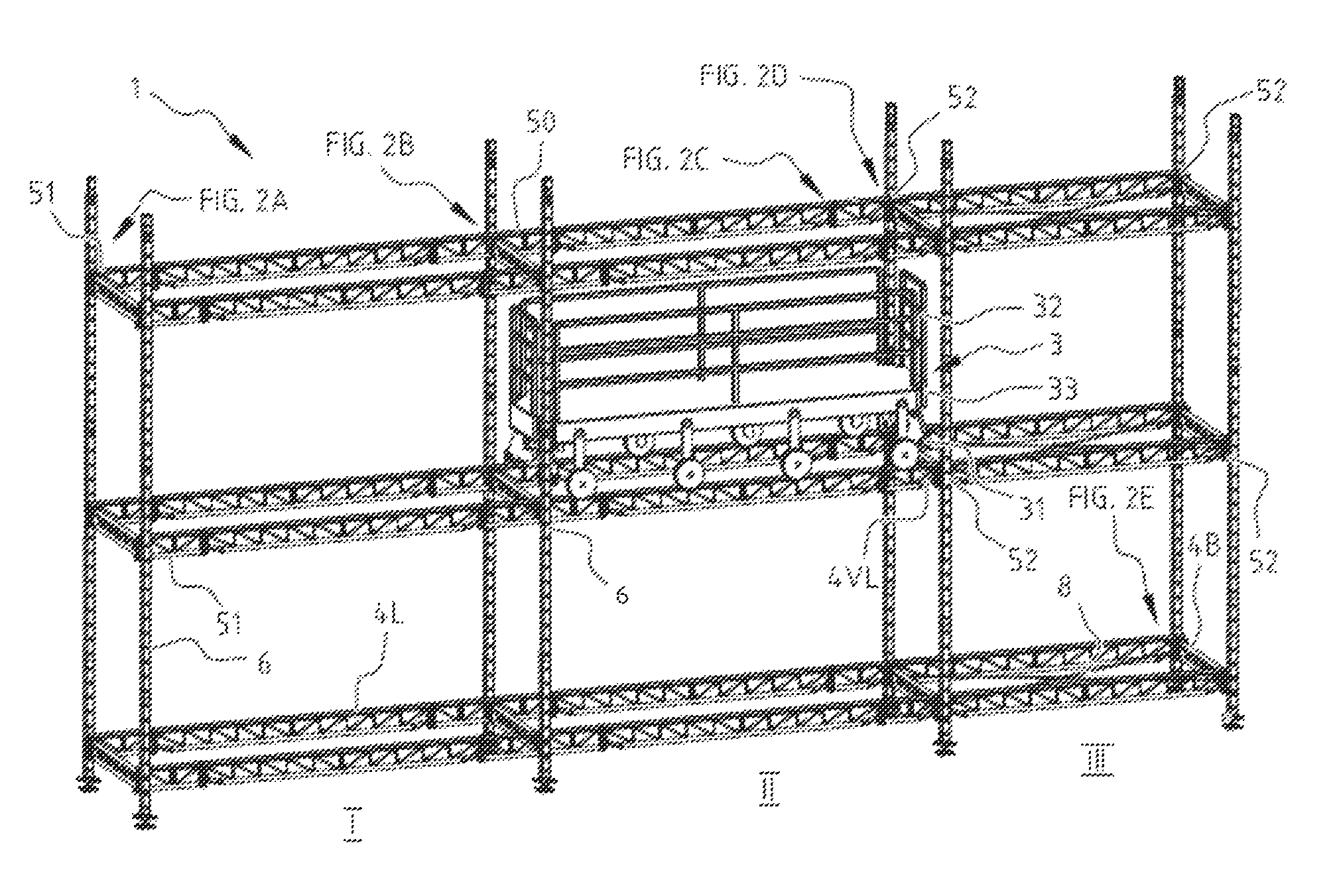
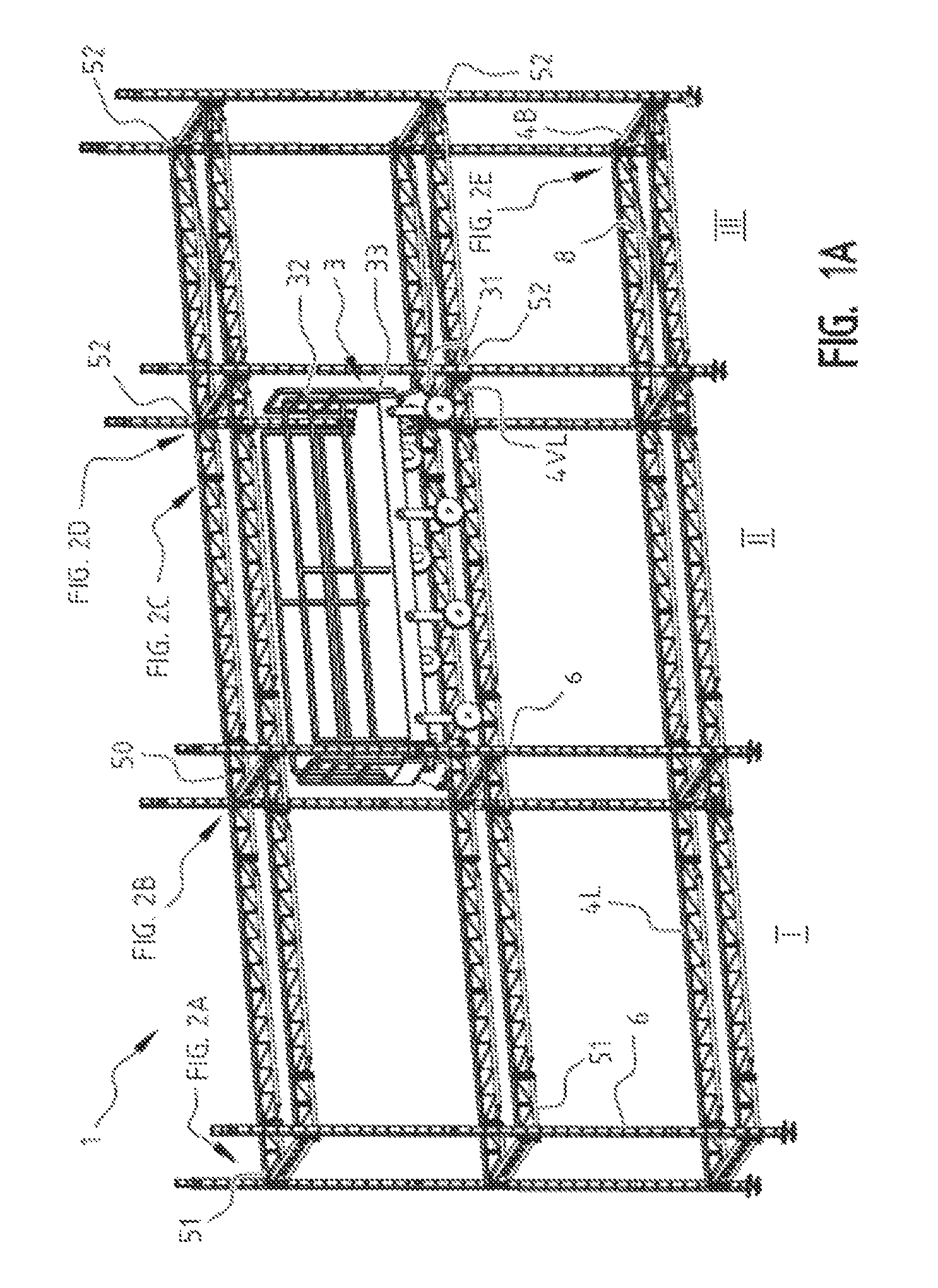
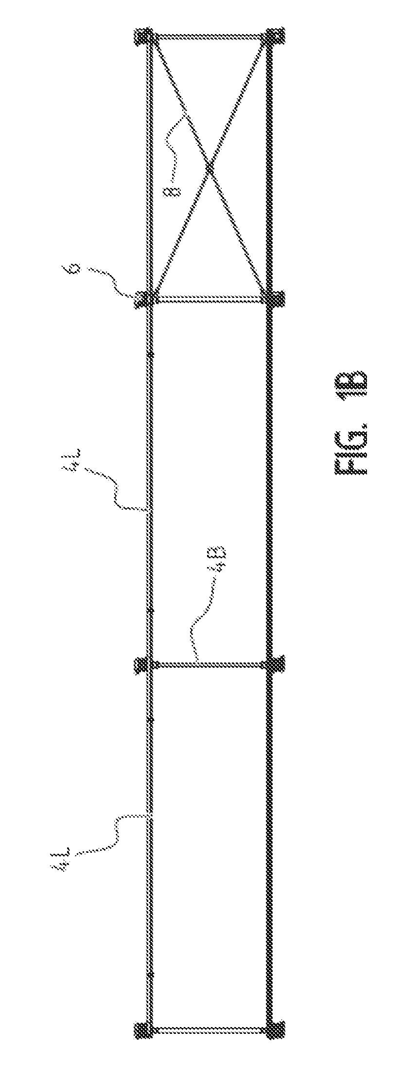
[0112]FIG. 1A shows a scaffold according to preferred embodiments of the present invention. The scaffold comprises rows and columns (I, II, III) of scaffold sections. Each of these scaffold sections is defined substantially by corresponding uprights 6, lengthwise ledgers 4L and transverse ledgers 4B. The scaffold sections can further be strengthened by the use of diagonals 8. At the bottom the up...


PUM

PropertyMeasurementUnit
distanceaaaaaaaaaa
distanceaaaaaaaaaa
distanceaaaaaaaaaa

Abstract

A scaffold comprising at least two horizontally adjacent scaffold sections, the scaffold sections being defined substantially by lengthwise ledgers, transverse ledgers and uprights, characterized in that the scaffold comprises a guide adapted to be able to displace in substantially horizontal direction therealong a displaceable platform corresponding thereto and guided thereby; a method for erecting the scaffold, and a mobile platform.

Description

[0001]The present invention relates to the field of scaffolding constructions, elements thereof and methods for erection thereof.BACKGROUND[0002]It is known that erection and dismantling of a scaffold is very labour-intensive. This means that a relatively large amount of time is lost in the erection of particularly larger scaffolds. The physical load for people erecting the scaffold is further a heavy one, so that many people can only perform this task for a limited part of their life.[0003]There is a need for scaffold systems which can be erected and dismantled relatively quickly.SUMMARY OF THE INVENTION[0004]It is an object of the present invention to provide a scaffold, scaffolding elements and methods for erecting a scaffold which solve at least one of the above stated problems.[0005]The Belgian patent applications BE 20100443 and BE 20100442, respectively titled “A lift unit for scaffold, methods for ascending and descending in a scaffold with the lift unit, methods for erectin...

Claims


Application Information

Patent Timeline
Patent Type & Authority Patents(United States)
IPC IPC(8): E04G1/14E04G5/00E04G5/14E04G1/15
CPCE04G1/15E04G5/00E04G5/147Y10T29/49826E04G5/007
Inventor KEERSMAEKERS, MARC
Owner KEERSMAEKERS MARC
Why Eureka
Try Eureka