Projection apparatus

a projection apparatus and rear projection technology, applied in the direction of projectors, mirrors, instruments, etc., can solve the problem of not being able to arrange any further deflection mirrors between the screens, and achieve the effect of simple design, simplified overall optical configuration and thus overall geometric symmetry

Active Publication Date: 2017-02-28
YOUNG OPTICS
View PDF21 Cites 4 Cited by
  • Summary
  • Abstract
  • Description
  • Claims
  • Application Information

AI Technical Summary

Benefits of technology

[0008]According to the invention, the object is achieved in that the projection optics have a reflective Fresnel mirror. This Fresnel mirror makes it possible to set a greater deflection of the light beams in the area remote from the axis (that is to say for the upper area of the screen), as a result of which the maximum incidence angle on the screen is reduced and can be set such that, for example in the case of a screen which has a transmissive Fresnel pane, it is no greater than the maximum permissible incidence angle for the transmissive Fresnel pane. It is thus possible to achieve a small foot height for the rear projection apparatus while maintaining the physical depth at the same time wherein, furthermore, an excellent image display is achieved since the screen can have just one transmissive Fresnel pane. In particular, the necessary beam deflection on the screen can be achieved exclusively by one transmissive Fresnel pane of the screen. The transmissive Fresnel pane may extend over the entire screen.
[0033]If the projection optics contain a deflection mirror, which, in particular, is provided between the output imaging elements, and makes it possible for the angle between the optical axis of the imaging elements of the projection optics before the deflection mirror and the optical axis of the imaging elements of the projection optics after the deflection mirror to be less than or equal to 90°, then the projection optics are optimally integrated in the rear projection apparatus. The advantageous introduction of the deflection mirror into the projection optics means that, for example, parts of the projection optics together with an illumination module, for example, can be positioned underneath the lower edge of the screen but above the optical axis of the aspherical first mirror, to be precise in such a way that parts of the projection optics are positioned at right angles, or at an angle of less than 90° to the optical axis of the second aspherical mirror. These measures mean that the foot height of the rear projection apparatus can be set at virtually zero, or the physical depth of the rear projection apparatus is governed only by the size of the first aspherical mirror.

Problems solved by technology

In particular, it is possible not to arrange any further deflection mirror between the screen and the Fresnel mirror.

Method used


Image

  • Projection apparatus
  • Projection apparatus
  • Projection apparatus

Examples


Embodiment Construction

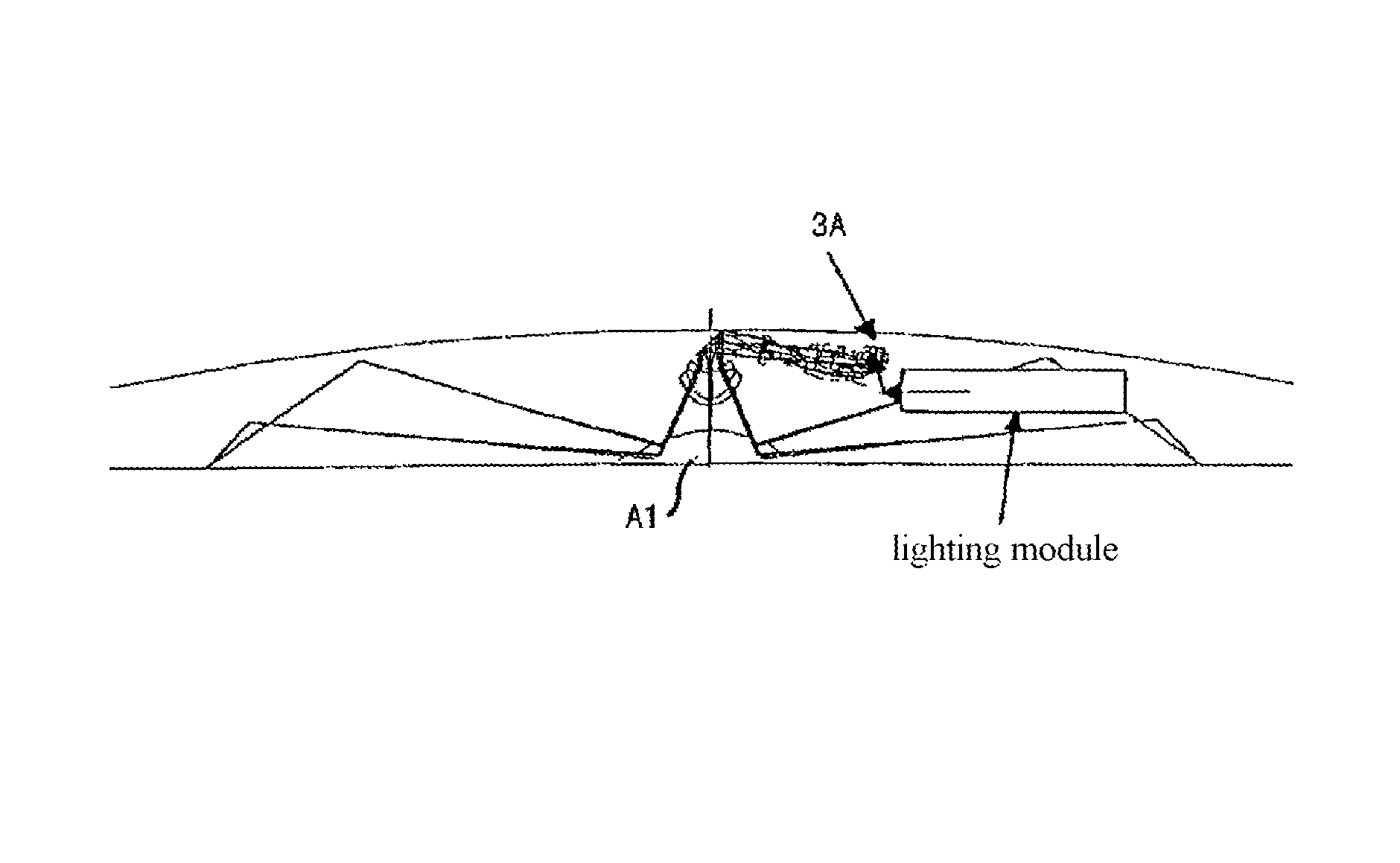
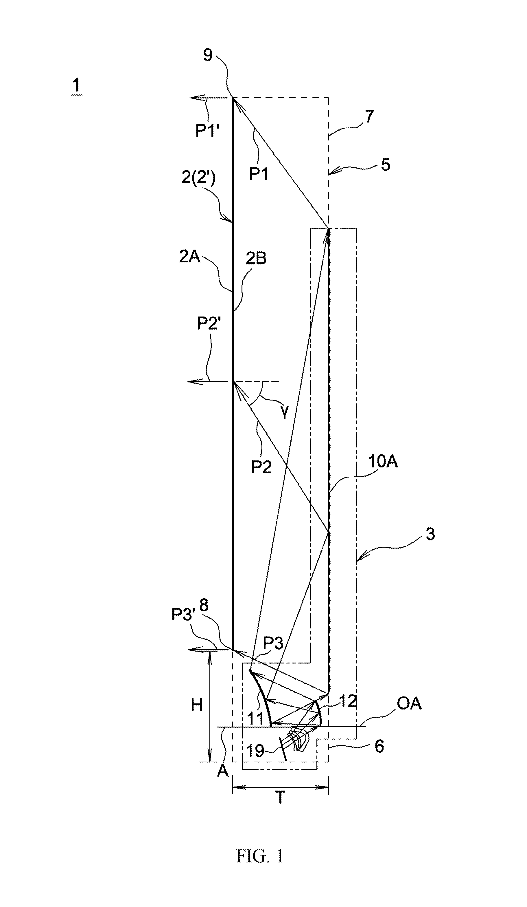
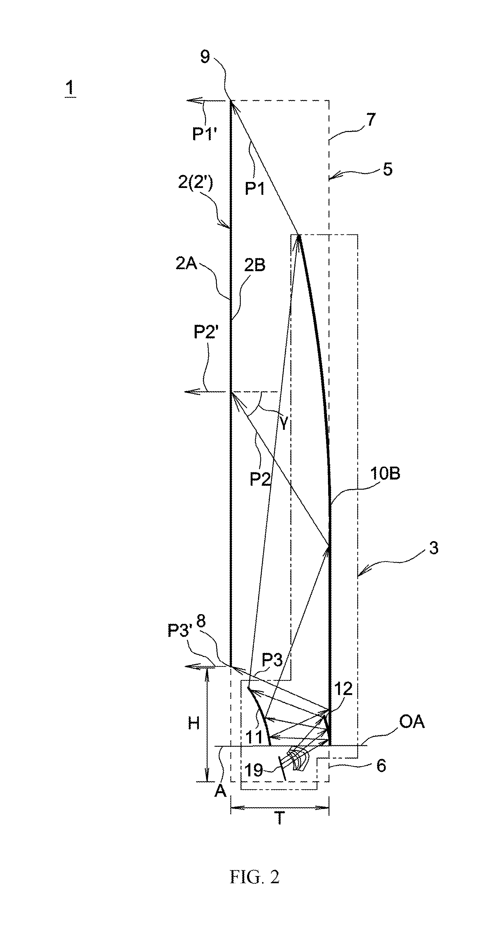
[0043]In the embodiment shown in FIGS. 1 and 2, the rear projection apparatus 1 comprises a screen 2 with a front face (2A) and a rear face (2B), projection optics 3, an image module 4 and a housing 5, which is represented by dashed lines in FIG. 1.

[0044]The projection optics 3 are arranged in the housing 5 of the rear projection apparatus 1, with the housing 5 having a foot part 6 and a screen part 7. The depth T of the rear projection apparatus is about 140 to 150 mm or 150 to 160 mm, and the front height H of the foot part is only about 140 mm. The height of the screen 2, which is illustrated as being rectangular, that is to say the distance from the lower edge 8 to the upper edge 9 of the screen 2 is in this case about 747 mm. The width of the screen (at right angles to the plane of the drawing in FIG. 1) is about 1328 mm which means that the screen 2 has a diagonal of about 1524 mm.

[0045]The projection optics 3 of the rear projection apparatus 1, or the projection optics 3 with...


PUM


Abstract

A projection apparatus includes an image-producing element and projection optics. The image-producing element produces at least one image, and the projection optics has free-form areas for magnifying and reflecting the image toward an viewer for observation. The projection optics includes at least a first mirror and a second mirror, the image is reflected by the first mirror and the second mirror in succession, no deflection mirror is disposed between the viewer and the second mirror, and the first mirror and the second mirror are in the form of a non-rotationally symmetrical system.

Description

CROSS-REFERENCE TO RELATED APPLICATIONS[0001]This application is a continuation of U.S. application Ser. No. 12 / 524,535, filed Sep. 9, 2009, which is a National Stage filing of International Patent Application No. PCT / EP2008 / 000596, filed Jan. 25, 2008, which claims priority to German Application No. 10 / 2007 / 003797.1, filed Jan. 25, 2007, and German Application No. 10 / 2007 / 006094.9, filed Feb. 7, 2007, the entire disclosures of which are incorporated herein by reference.BACKGROUND OF THE INVENTION[0002]1. Field of the Invention[0003]The present invention relates to a rear projection apparatus having a screen, projection optics and an image module for production of an image which is projected by means of the projection optics from the rear onto the screen, such that a viewer who is located in front of the screen can perceive the image which is projected onto the screen. The invention also relates to a method for a rear projection apparatus such as this.[0004]2. Description of the Rel...

Claims


Application Information

Patent Timeline
Patent Type & Authority Patents(United States)
IPC IPC(8): G02B17/06G03B21/28G02B5/08G02B17/08G03B21/10G02B13/16
CPCG03B21/28G02B5/08G02B17/0605G02B17/0615G02B17/0812G02B17/0816G02B17/0832G03B21/10G02B13/16
Inventor PIEHLER, EBERHARDSCHROETER, GUDRANBENEDIX, GUENTHERBLEI, GERTRUDMAACK, THOMAS
Owner YOUNG OPTICS
Why Eureka
Try Eureka