Coupling structure for input devices

a technology of coupling structure and input device, which is applied in the field of coupling structure of input device, can solve the problems of further difficulty in making the structure thinner, and the flexural amount of the locking claw may exceed an acceptable amoun

Active Publication Date: 2017-02-28
LENOVO PC INT
View PDF11 Cites 2 Cited by
  • Summary
  • Abstract
  • Description
  • Claims
  • Application Information

AI Technical Summary

Benefits of technology

[0007]Further, in the above-mentioned structure, the locking hole and the locking claw are engaged with each other by sliding them. However, in order to further improve the assembling efficiency, a structure is considered in which, for example, the locking hole and the locking claw are pressed in the up-and-down direction without sliding them to engage them directly. In this structure, however, an engaging claw is required to be flexed and deformed to some extent when engaged in the locking hole. In other words, it is necessary to further increase the amount of upward projection in order to secure a sufficient flexural amount of the engaging claw, and this makes it further difficult to make the structure thinner. In addition, in order to prevent the engaging state from being released when an impact is given, it is necessary to set a sufficient engagement allowance between the locking hole and the locking claw, and there is concern that the flexural amount of the locking claw may exceed an acceptable amount during the assembly to damage the locking claw.

Problems solved by technology

In the above-mentioned structure, since the locking hole and the locking claw project towards a coupling direction in which the frame and the base plate overlap, there is a problem that it is difficult to make the structure thinner.
In other words, it is necessary to further increase the amount of upward projection in order to secure a sufficient flexural amount of the engaging claw, and this makes it further difficult to make the structure thinner.
In addition, in order to prevent the engaging state from being released when an impact is given, it is necessary to set a sufficient engagement allowance between the locking hole and the locking claw, and there is concern that the flexural amount of the locking claw may exceed an acceptable amount during the assembly to damage the locking claw.

Method used


Image

  • Coupling structure for input devices
  • Coupling structure for input devices
  • Coupling structure for input devices

Examples


Embodiment Construction

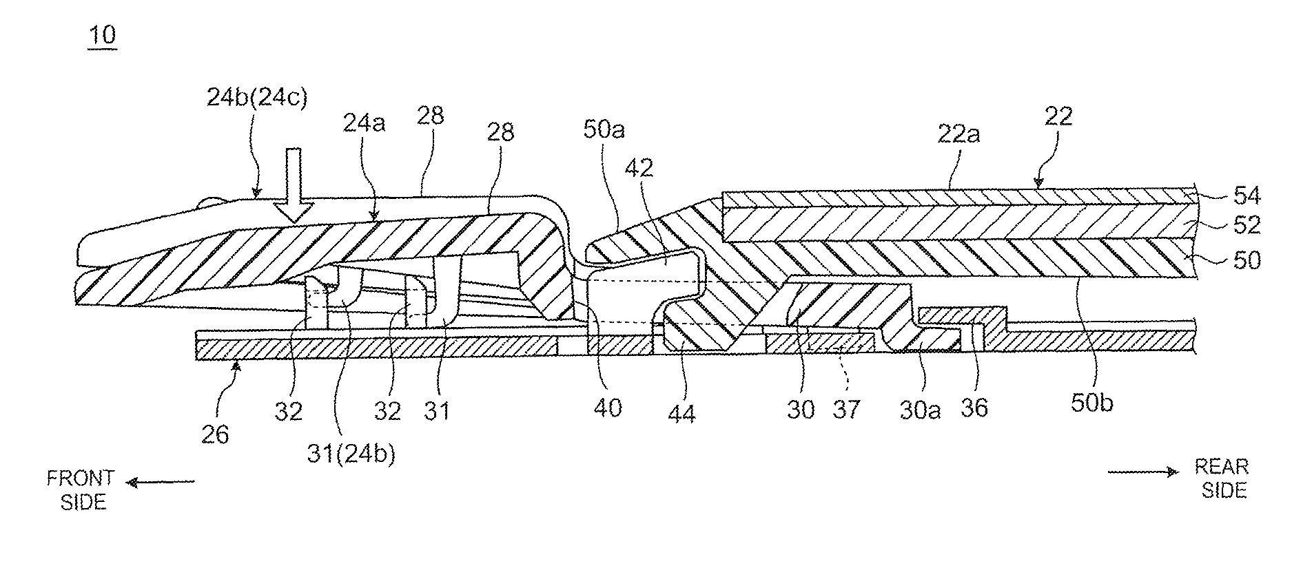
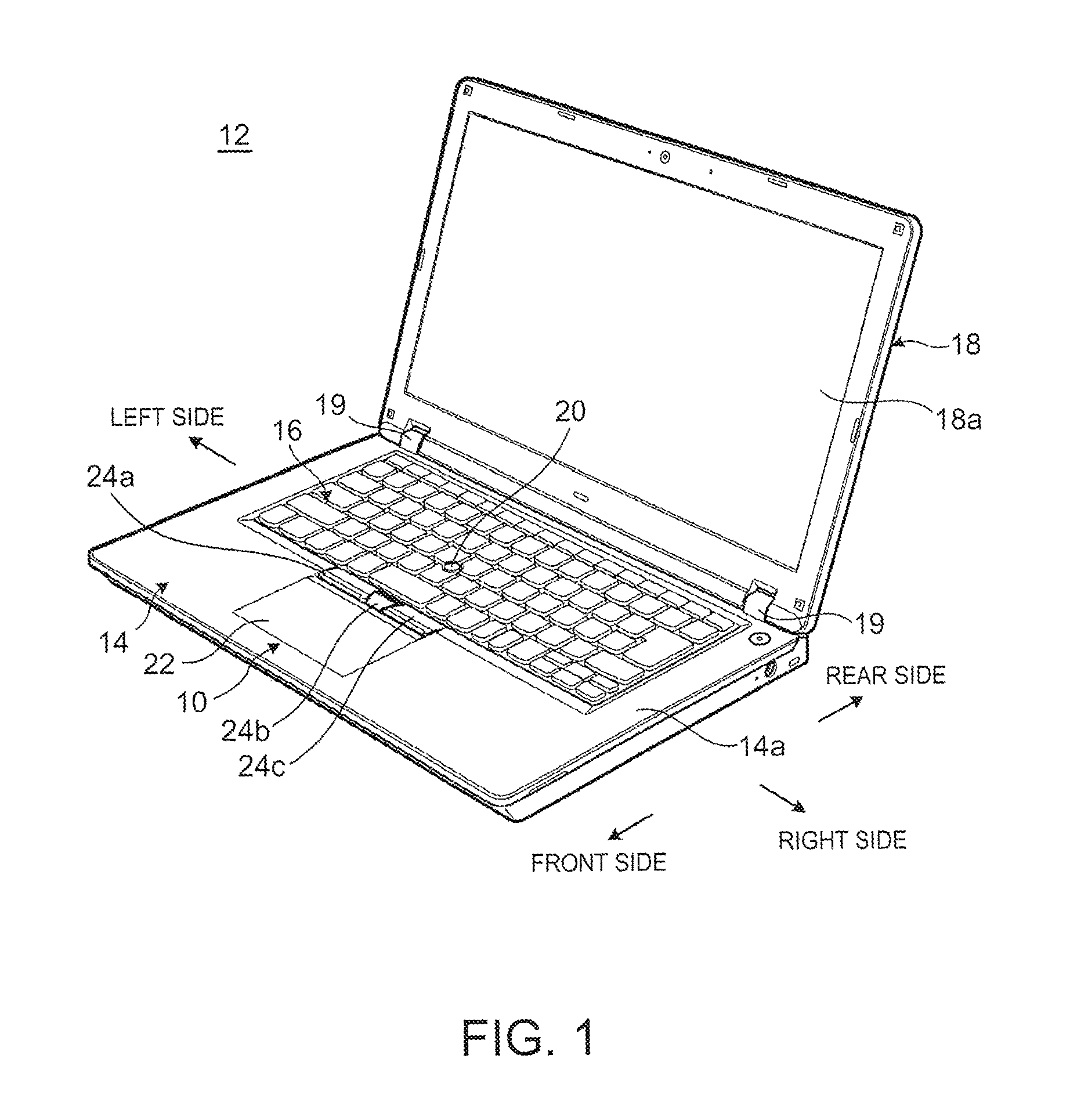
[0029]Referring now to the drawings and in particular to FIG. 1, there is depicted a perspective view of an electronic device 12 having an input device 10 in accordance with a preferred embodiment of the present invention. The following description will be made while referring to the near side as the front side (front), the far side as the rear side (rear), the thickness direction of a main body chassis 14, which constitutes the electronic device 12, as the up-and-down direction, and the width direction thereof as the right-and-left direction, based on the usage pattern of the input device 10 in the electronic device 12 shown in FIG. 1.

[0030]As shown in FIG. 1, the electronic device 12 is a laptop PC including the main body chassis 14 having the input device 10 and a keyboard device 16, and a display chassis 18 having a display device 18a such as a liquid crystal display. The display chassis 18 is connected openably and closably to the main body chassis 14 by a pair of right and lef...


PUM


Abstract

A coupling structure capable of coupling a metal plate-like member and a resin chassis member with high assembling efficiency and sufficient coupling strength while preventing damage to parts is disclosed. The coupling structure is a structure for coupling a housing plate as a resin chassis member to a base plate as a metal plate-like member in a direction to overlap the housing plate with the base plate. The housing plate includes a latch having a pair of arm members extending along a direction parallel with a coupling face to the base plate and whose distal ends are spaced out from each other, and the base plate includes a coupling hook formed upright toward the side of the housing plate and engaged between the pair of arm members.

Description

PRIORITY CLAIM[0001]The present application claims benefit of priority under 35 U.S.C. §§120, 365 to the previously filed Japanese Patent Application No JP2014-233738 with a priority date of Nov. 18, 2014, which is incorporated by reference herein.BACKGROUND OF THE INVENTION[0002]1. Technical Field[0003]The present invention relates to input devices having a coupling structure in general, and particularly to a coupling structure for coupling a resin chassis member to a metal plate-like member in a direction to overlap each other.[0004]2. Description of Related Art[0005]For an input device having a coupling structure to couple a resin keyboard frame to a metal base plate in a direction to overlap each other, a locking hole opened downward or laterally in the lower surface of a frame is provided, and a locking claw projecting upward towards the frame side is provided on the top face of a base plate. Then, the frame and the base plate are slide relative to each other after the locking ...

Claims


Application Information

Patent Timeline
Patent Type & Authority Patents(United States)
IPC IPC(8): G06F1/16
CPCG06F1/1679G06F1/1684G06F1/1616
Inventor DOI, TOSHIHISAHORIUCHI, MITSUOSHINOHARA, EIJI
Owner LENOVO PC INT
Why Eureka
Try Eureka