Hot melt glue gun with an automatic glue stick feeding structure

Active Publication Date: 2017-03-07
HOMEEASE INDAL CORP
View PDF4 Cites 12 Cited by
  • Summary
  • Abstract
  • Description
  • Claims
  • Application Information

AI Technical Summary

Benefits of technology

[0005]The primary objective of the present invention is to provide a hot melt glue gun with an automatic glue stick feeding structure to permit forward feeding of a glue stick when a press button is slightly pressed. Furthermore, when the press button is not pressed, the glue stick moves rearwards a small distance, such that the glue stick will not press the molten glue in a hot melt chamber, avoiding continuous dripping of the molten glue through a nozzle.

Problems solved by technology

Furthermore, when the press button is not pressed, the glue stick moves rearwards a small distance, such that the glue stick will not press the molten glue in a hot melt chamber, avoiding continuous dripping of the molten glue through a nozzle.

Method used


Image

  • Hot melt glue gun with an automatic glue stick feeding structure
  • Hot melt glue gun with an automatic glue stick feeding structure
  • Hot melt glue gun with an automatic glue stick feeding structure

Examples


Embodiment Construction

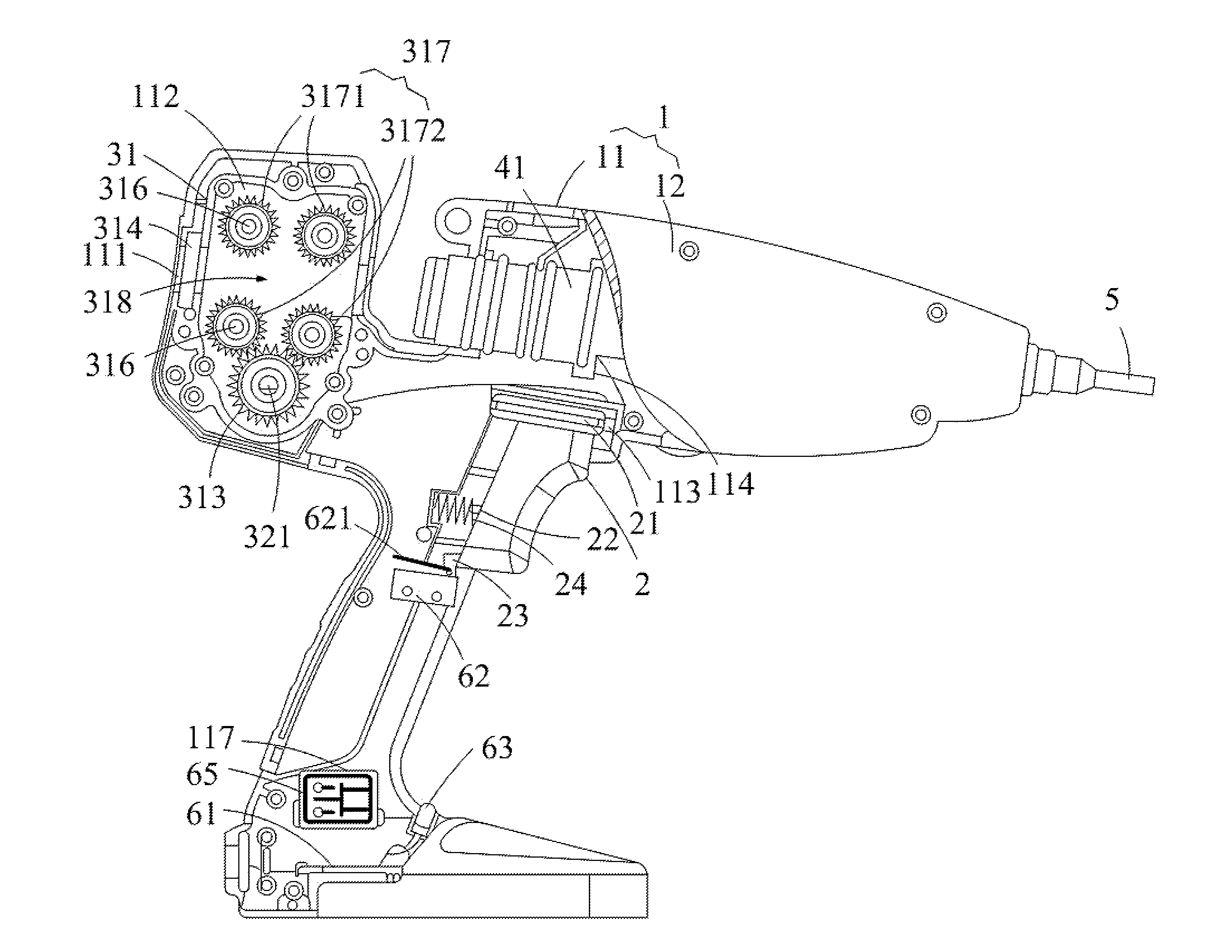
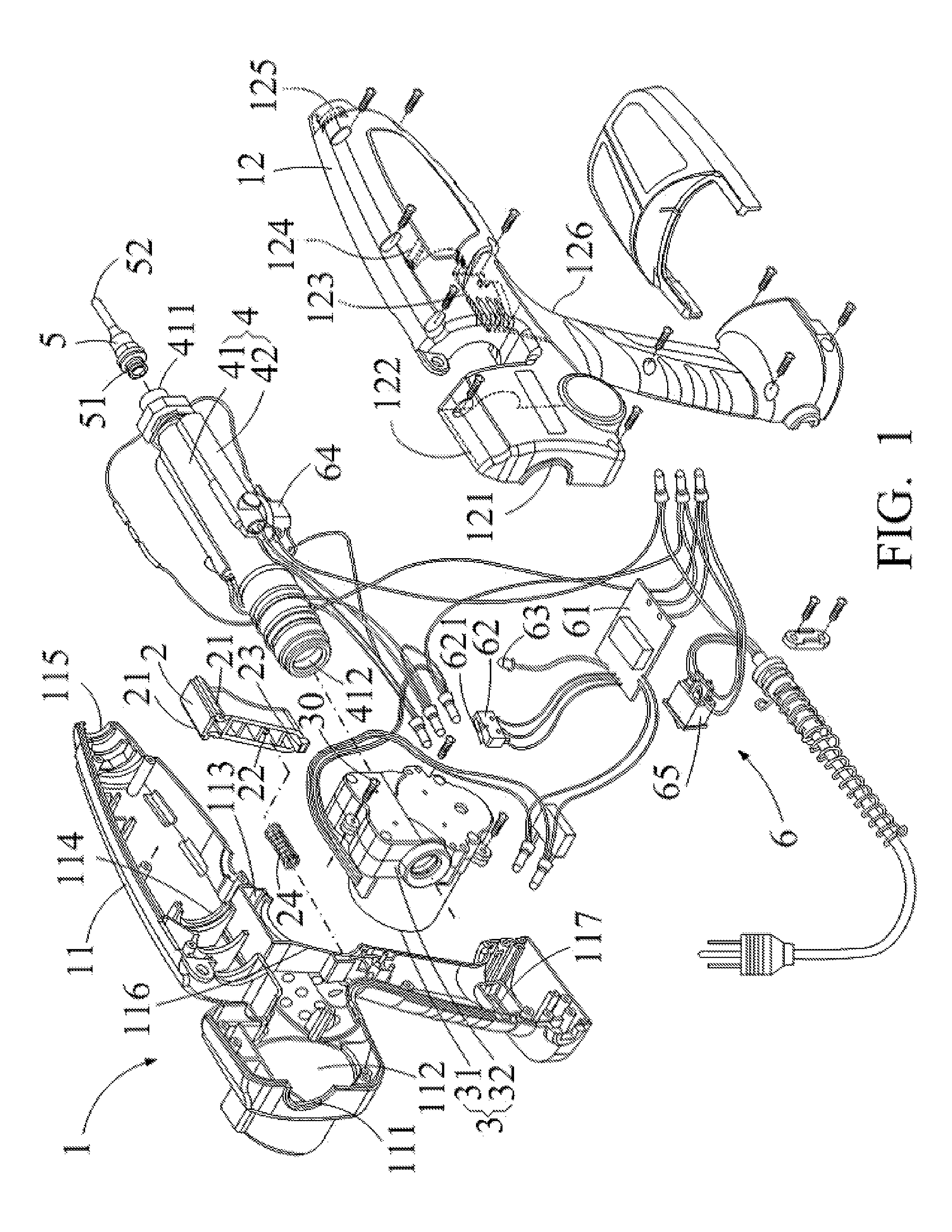
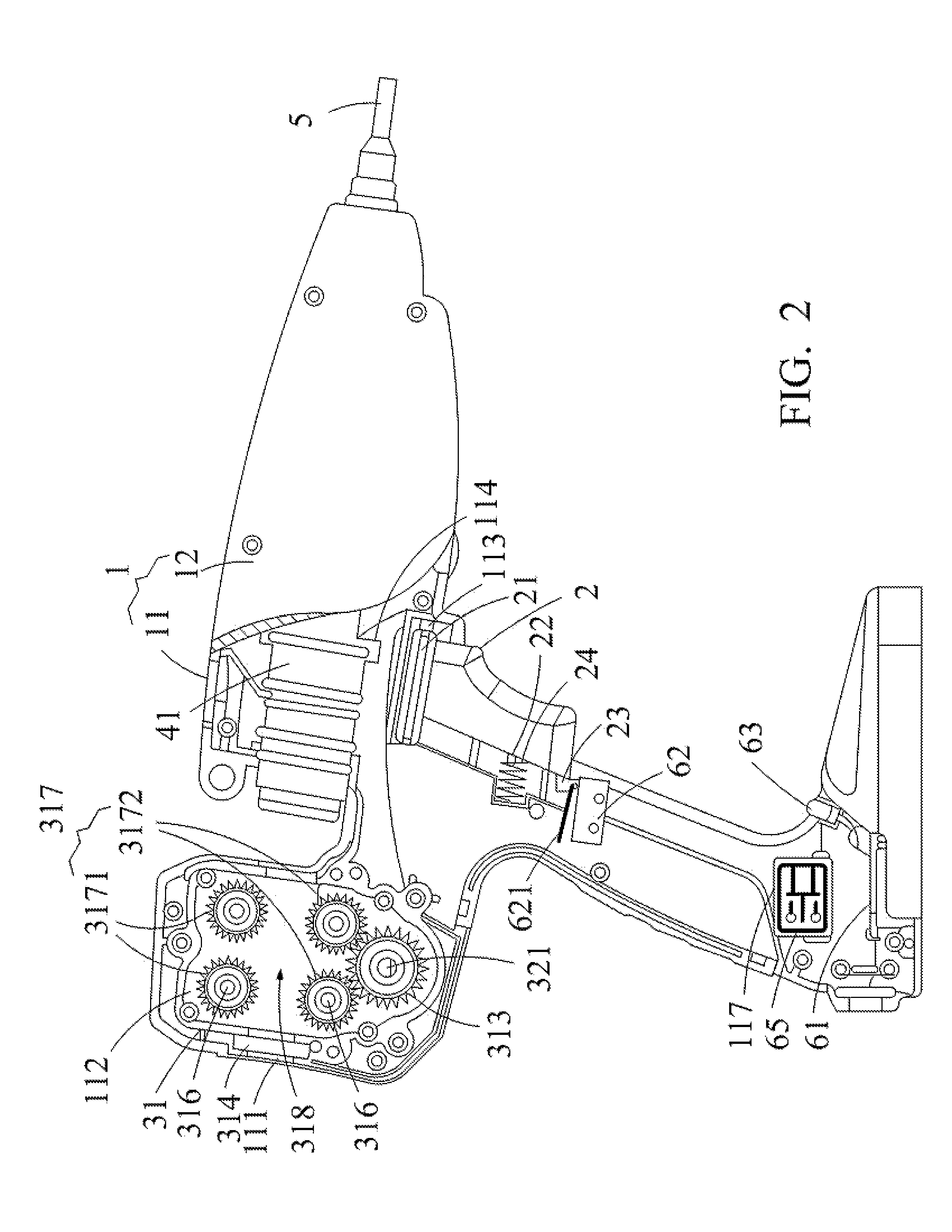
[0017]With reference to FIGS. 1 and 2, a hot melt glue gun with an automatic glue stick feeding structure according to the present invention includes a housing 1, a press button 2, an automatic glue stick feeding device 3, a hot melt unit 4, a nozzle 5, and a control unit 6.

[0018]The housing 1 is gun-shaped and includes a left housing part 11 having a hole 117 and a right housing part 12. Each of the left housing part 11 and the right housing part 12 includes a semi-circular inlet 111, 121, a receiving compartment 112, 122, a channel 113, 123, a plurality of semi-circular clamping blocks 114, 124, a semi-circular through-hole 115, 125, and a notch 116, 126. After the left housing part 11 and the right housing part 12 have been assembled to form the housing 1, the semi-circular inlets 111 and 121 together form a circular inlet, the semi-circular clamping blocks 114 and 124 together form a circular clamping block, the semi-circular through-holes 115 and 125 together form a circular th...


PUM


Abstract

A hot melt glue gun with an automatic glue stick feeding structure includes a gun-shaped housing, a press button, an automatic glue stick feeding device, a hot melt unit, a nozzle, and a control unit. The automatic glue stick feeding device includes a casing and a synchronous motor having a transmission shaft. The casing includes a transmission gear, an inlet, and at least one gear train having upper and lower gears and a passage. The control unit includes a control printed circuit board, a micro switch, a forward relay output control portion, and a rearward relay output control portion. A glue stick is moved forwards when a user slightly presses the press button. When the press button is not pressed, the glue stick moves rearwards, avoiding continuous dripping of the molten glue through a nozzle.

Description

BACKGROUND OF THE INVENTION[0001]The present invention relates to a hot melt glue gun and, more particularly, to a gun-shaped hand tool using electricity to generate high heat for melting a glue stick.[0002]With reference to FIG. 6, a conventional hot melt glue gun includes a press button 1′ slidable relative to a track of a housing of the hot melt glue gun by provision of a groove 11′. A limiting pin 21′ on an end of an arm 2′ is inserted into a hole of the press button 1′. The arm 2′ is pivotable relative to the housing of the hot melt glue gun about a pivot axis at an intermediate portion of the arm 2′. The other end of the arm 2′ can pull an end of a follower plate 3′. The other end of the follower plate 3′ is connected to a holding block 4′ that is connected to a feeding seat 5′ via a pin 41′. The holding block 4′ can pivot about the pin 41′ to actuate the feeding seat 5′ to move rectilinearly. The feeding seat 5′ includes a forwardly protruding leg 51′ around which a spring 52...

Claims


Application Information

Patent Timeline
Patent Type & Authority Patents(United States)
IPC IPC(8): B05C17/005
CPCB05C17/0053B05C17/00536
Inventor LEE, GRACE
Owner HOMEEASE INDAL CORP
Why Eureka
Try Eureka