Motor control device, motor control system, motor control module and refrigerating unit

A technology of motor control and control system, applied in the fields of motor control system, motor control module, refrigeration device, and motor control device, can solve the problem of complicated device, inability to adjust the error between the motor rotor shaft and the control shaft, and the undocumented load torque estimation method and other problems to achieve the effect of reducing the impact of switching

Active Publication Date: 2010-01-27
HITACHI JOHNSON CONTROLS AIR CONDITIONING INC
View PDF2 Cites 55 Cited by
  • Summary
  • Abstract
  • Description
  • Claims
  • Application Information

AI Technical Summary

Problems solved by technology

[0008] In the technology of Patent Document 1, in order to determine the voltage in the synchronous operation mode, the change of the load torque is estimated from the change of the current flowing through the motor, but the method of estimating the load torque before and after switching is not described.
In addition, in order to detect the induced voltage phase of the motor, an additional circuit and a s...

Method used


Image

  • Motor control device, motor control system, motor control module and refrigerating unit
  • Motor control device, motor control system, motor control module and refrigerating unit
  • Motor control device, motor control system, motor control module and refrigerating unit

Examples


no. 1 approach

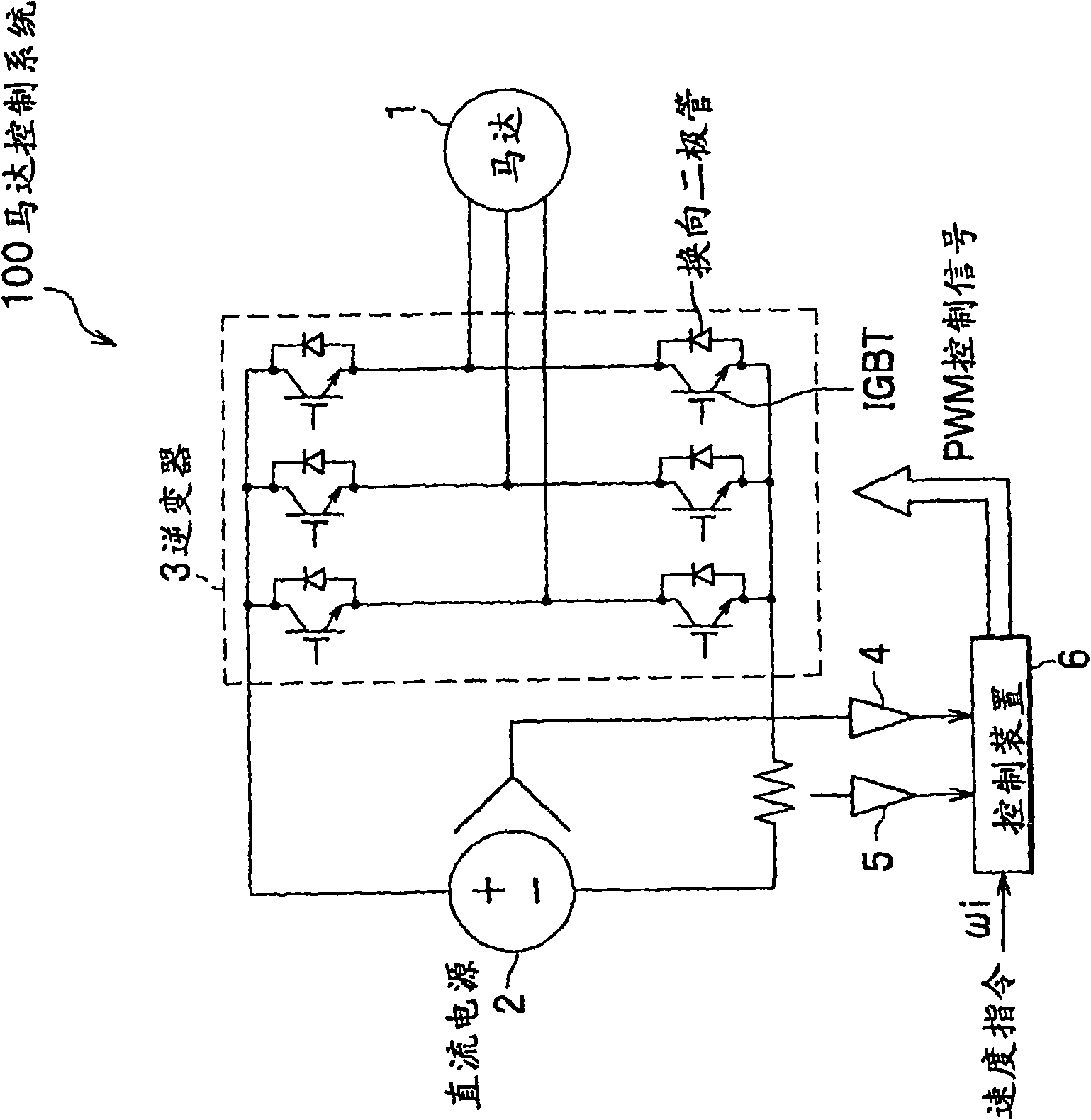
[0031] figure 1 It is a configuration diagram of the motor control system according to the first to third embodiments of the present invention.

[0032] The motor control system 100 includes: a permanent magnet synchronous motor 1; a DC power supply 2; an inverter 3 that converts DC power to AC power; a DC voltage detector 4 that detects the voltage of the DC power supply 2; A DC current detector 5 that detects the current on the DC side; and a control device 6.

[0033] Motor 1 is a permanent magnet synchronous motor.

[0034] The DC power supply 2 is a converter (rectifier) ​​or a battery that converts AC power supplied from a commercial power supply into DC power, and supplies power to the DC side of the inverter 3.

[0035] The inverter 3 includes: six IGBTs (Insulated Gate Bipolar Transistors); and a commutation diode connected to the collector and emitter of each IGBT.

[0036] In addition, the control device 6 processes the detection signals of the DC voltage detector 4 and the...

no. 2 approach

[0087] Picture 12 It is a detailed functional block configuration diagram of the voltage command controller 12 (12b) as the motor control device of the second embodiment of the present invention. versus Figure 4 The difference is that, as shown in equation (6), the voltage command value calculation is changed to the sum of the output of the vector calculator 42 and the output of the current controllers 39 and 40. The current reproduction calculation and phase estimation processing are the same as in the first embodiment.

[0088] V dc * = r * I dc * - ω 1 * Lq * I qc * + ΔV dc V qc * = r * I qc * + ω 1 * Ld * I dc * + ω 1 * Ke * + ΔV qc . . . ( 6 )

[0089] Here, ΔVdc and ΔVqc are the outputs of the current controllers 39 and 40.

[0090] In addition, the start sequence, the current vector phase adjustment in the synchrono...

no. 3 approach

[0092] The structural elements of the motor control device of the third embodiment of the present invention are the same as figure 1 The parts shown are the same, but the vector control method inside the control device 6 is different.

[0093] (The overall structure of control)

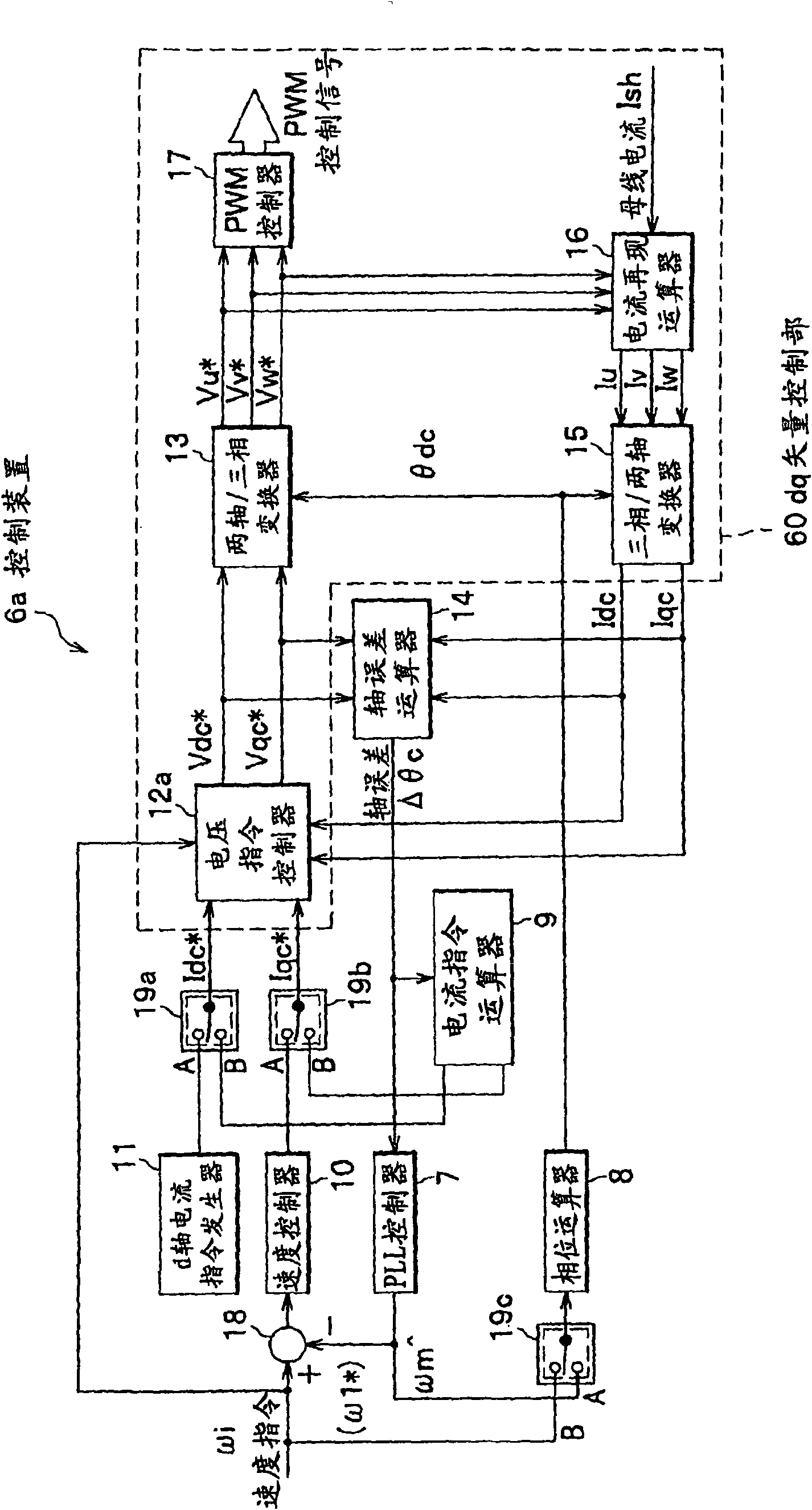
[0094] Figure 13 It is a functional block configuration diagram of the control device 6 (6b) as the third embodiment of the present invention. In addition, with figure 2 The parts with the same number perform the same actions.

[0095] versus figure 2 The different part is: the qc-axis current command value Iqc in the sensorless mode is calculated from the low-pass filter 52 * ; And the PLL controller 7 that performs estimation processing of the rotation speed ωm of the motor 1 ( figure 2 ) Is changed to a speed error calculator 50 for calculating a speed error and an adder 51 for calculating the sum of the speed error and the speed command.

[0096] That is, the speed error calculator 50 performs a prop...


PUM


Abstract

The invention provides a motor control device, a motor control system, a motor control module and a refrigerating unit, capable of reducing switching shock when switching from synchrony operation mode to non-position sensor mode. In a control device 6a comprising a dc vector control device for controlling rotating speed of permanent magnet synchronous motor consistent with speed instruction value omega i through an inverter, comprising a synchrony operation mode for driving the permanent magnet synchronous motor together with a rotating angle theta m' obtained by integraling the speed instruction value; and a non-position sensor mode for proceeding feedback control to rotating angle theta m of the permanent synchronous motor, comprising a switcher 19 that speculating shaft error (delta theta c) of the stator shaft of the permanent magnet synchronous motor and control system shaft of the dq vector control part, and when the speculated shaft error almost consistent with phase difference of current instruction value, the synchronous rotating mode is switched into the non-position sensor mode.

Description

Technical field [0001] The invention relates to a motor control device, a motor control system, a motor control module and a refrigeration device. Background technique [0002] In the position sensorless drive device of a permanent magnet synchronous motor (hereinafter referred to as "motor"), the following method is known: at the beginning of starting, a current of a predetermined amplitude is passed through the motor while gradually increasing the output of the inverter Frequency, accelerate the motor to a predetermined speed (called synchronous operation mode), and then estimate the shaft error between the motor rotor shaft and the control system shaft based on the voltage and current information applied to the motor, and switch to control the estimated shaft error to the predetermined Value mode (called sensorless operation mode). [0003] In this method, when the operation mode is switched at a predetermined speed, the rotor shaft of the motor in the synchronous operation mod...

Claims


Application Information

Patent Timeline
IPC IPC(8): H02P21/00H02P21/14H02P6/18H02P6/06H02P6/08H02P6/182H02P6/21
Inventor 李东升能登原保夫岩路善尚栗田佳明
Owner HITACHI JOHNSON CONTROLS AIR CONDITIONING INC
Why Eureka
Try Eureka