Media flow method for transferring real-time data between asynchronous and synchronous networks

Inactive Publication Date: 2006-10-24
UTSTARCOM INC
View PDF25 Cites 58 Cited by
  • Summary
  • Abstract
  • Description
  • Claims
  • Application Information

AI Technical Summary

Benefits of technology

[0034]According to another aspect of the embodiments, a packetizing step may include creating one or more descriptors, where each descriptor inclu

Problems solved by technology

TDM arrangements may be less flexible than asynchronous approaches because time slots are allocated to particular streams.
One possible drawback to transmitting voice data over connectionless networks, or networks having connectionless portions, can be the potential for different portions of the same voice stream arriving out of sequence.
However, while such samples can be transmitted in order, because packets may travel along different legs of a network, a sample may arrive out of order.
Thus, a voice sample may never arrive at a desired destination.
This can be difficult to achieve with many conventional approaches.
One drawback associated with voice over packet can be the latency introduced by such approaches.
Transmission of the voice over packet can also introduce latency.
Routing from node to node, or along a switching path, can consume additional time.
Finally, a receiving destination can introduce delay.
Such computation steps can contribute significantly to latency.
A drawback to such approaches is that all routers/switches in the network must have such an advanced processing c

Method used


Image

  • Media flow method for transferring real-time data between asynchronous and synchronous networks
  • Media flow method for transferring real-time data between asynchronous and synchronous networks
  • Media flow method for transferring real-time data between asynchronous and synchronous networks

Examples


first embodiment

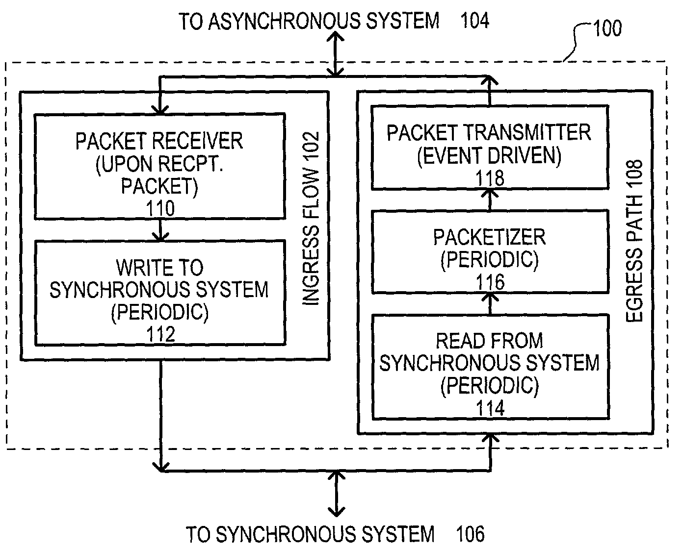
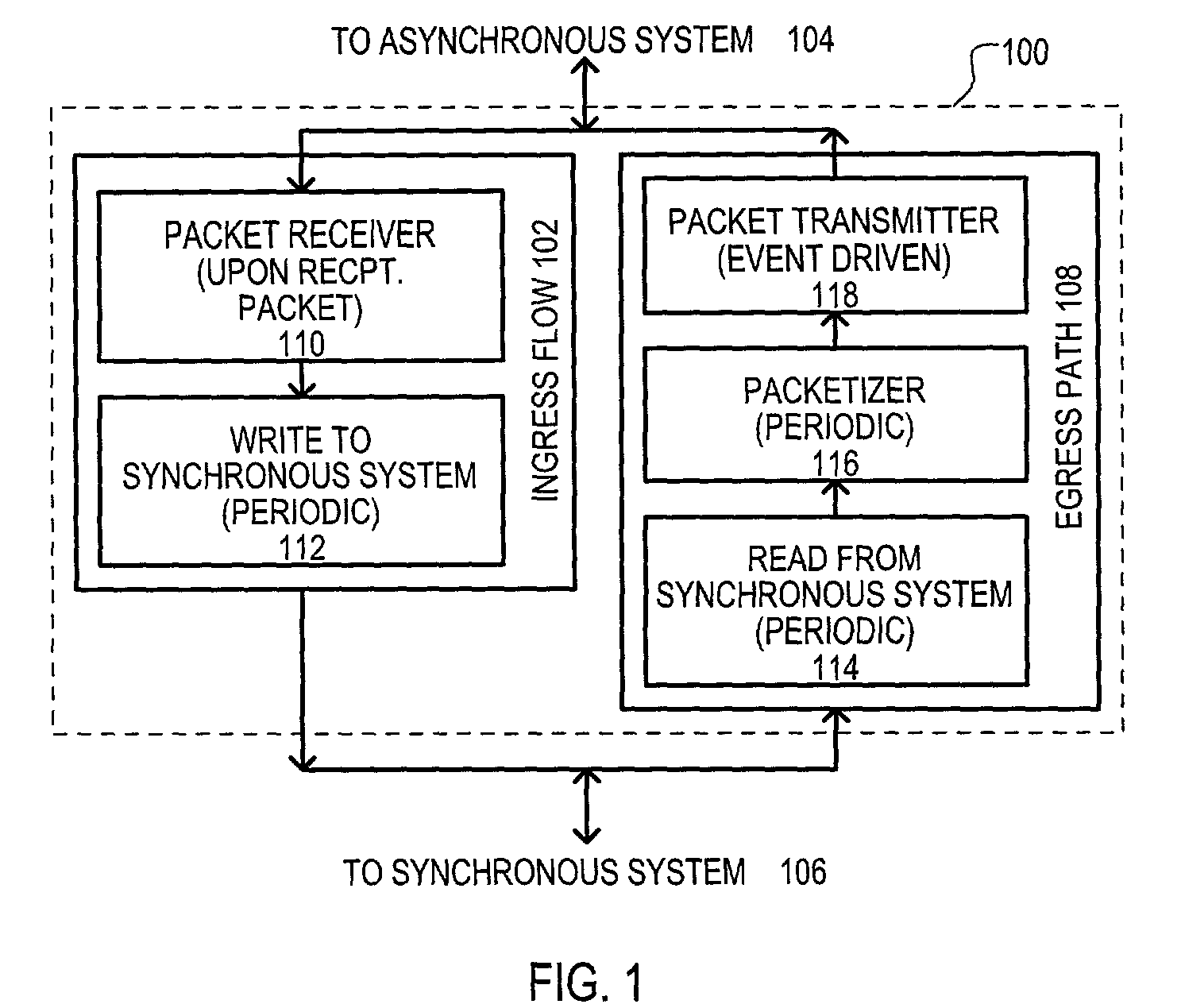
[0046]A method is set forth in FIG. 1, and designated by the general reference character 100. A method 100 may be represented by two “flows.” An ingress flow 102 may represent the processing of data received from an asynchronous system 104 for a synchronous system 106. An egress flow 108 may represent the processing of data received from a synchronous system 106 to an asynchronous system 104.

[0047]An ingress flow 102 may include a packet receiver 110 that may be invoked upon reception of a new packet from an asynchronous system 104. Data contained within such packets may be organized by a packet receiver 110 to account for asynchronous transmission delays. In one particular arrangement, data may be stored in a “jitter” buffer to account for the asynchronous rate at which data can be received and / or unpredictable aspects of a network. For example, such a buffering can organize packets of a stream that are out of order, account for lost packets, or account for arrival time jitter (di...

second embodiment

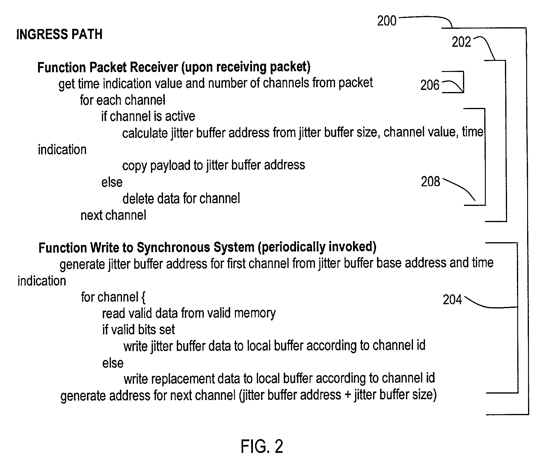
[0054]A second embodiment will now be described with reference to FIGS. 2, 3A and 3B, 4, and 5A and 5B. A pseudocode representation of an ingress path is set forth in FIG. 2, and designated by the general reference character 200. “Pseudocode,” a broad way of expressing the various elements of a flow, may be implemented into particular computer language code versions for use in a system employing a general processor. In addition, the described method can be implemented in a higher-level hardware designing language, to enable the preferred embodiment to be realized as an integrated circuit (IC) or a portion of an IC. Pseudocode is widely used in industry and textbooks to express methods and devices, and would be understood by one skilled in the arts of computer systems and / or hardware designing arts.

[0055]FIG. 2 shows an ingress path 200 that may include a packet receiver function 202 and a write to synchronous system function 204. It is noted that a packet receiver function 202 may b...

third embodiment

[0112]an ingress path will now be described with reference to FIGS. 6A to 6C. FIGS. 6A to 6C may be portions of a single pseudocode example for an ingress path. Thus, it is understood that the pseudocode of FIG. 6C may follow that of 6B, which may follow that of 6A.

[0113]Referring now to FIG. 6A an ingress path may process packets of at least two types: “simplex” packets that may include a payload for a single channel; and multiplex (MUX) packets that may include payloads for multiple channels.

[0114]In the example of FIG. 6A, an ingress path may be assumed to process packets transmitted according to a predetermined protocol, in this case UDP. Thus, particular fields from such a packet may be read to ascertain whether a packet is simplex or multiplex. In FIG. 6A, an initial step includes reading a UDP destination port value, a sequence number, and a timestamp value. Such a step is shown in FIG. 6A as 602.

[0115]A UDP destination port may provide an initial indication. Accordingly, an ...


PUM


Abstract

A system for transmitting real-time data between an asynchronous network (104) and a synchronous network (106) is disclosed. A method (100) may include an ingress path (102) for transmitting data from an asynchronous system (104) to a synchronous system (106), and an egress path (108) for transmitting data from a synchronous system (106) to an asynchronous system (104). An ingress path (102) may include a packet receiver (110) and write to synchronous system (112) steps. An egress path (108) may include read from synchronous system (114), packetizer (116), and packet transmitter (118) steps.

Description

TECHNICAL FIELD[0001]The present invention relates generally to systems for processing data transmitted over networks, and more particularly to systems in which data is transferred between an asynchronous system and a synchronous system.BACKGROUND OF THE INVENTION[0002]Data communication networks may be generalized into at least two types: asynchronous and synchronous. Performance characteristics and transmission latencies in synchronous networks are understood, and in many cases predictable. However, many asynchronous networks can be easier and less expensive to deploy and maintain than typical synchronous networks. In light of the convergence of disparate networks, there arises a need to provide methods and systems for interconnecting asynchronous networks with synchronous networks. Asynchronous networks typically operate under well known protocols, including by not limited to, the Transmission Control Protocol (TCP), Internet Protocol (IP), User Datagram Protocol (UDP) to name bu...

Claims


Application Information

Patent Timeline
IPC IPC(8): H04L12/56H04J3/06
CPCH04L47/10H04L47/22H04L47/283H04L49/90H04L49/901H04L49/9031H04L49/9023
Inventor ISUKAPALLI, SRIDHAR G. SHARMAPANDEY, PRADEEPSHAVER, MATTHEW D.SCHNEIDER, NEAL A.TSZTOO, GARY
Owner UTSTARCOM INC
Why Eureka
Try Eureka