

Drive system of synchronous motor
a technology of synchronous motors and drive systems, applied in the direction of electronic commutators, motor/generator/converter stoppers, dynamo-electric converter control, etc., can solve the problem of longer acceleration tim
- Summary
- Abstract
- Description
- Claims
- Application Information
AI Technical Summary
Benefits of technology
Problems solved by technology
Method used
Image

Examples
first embodiment
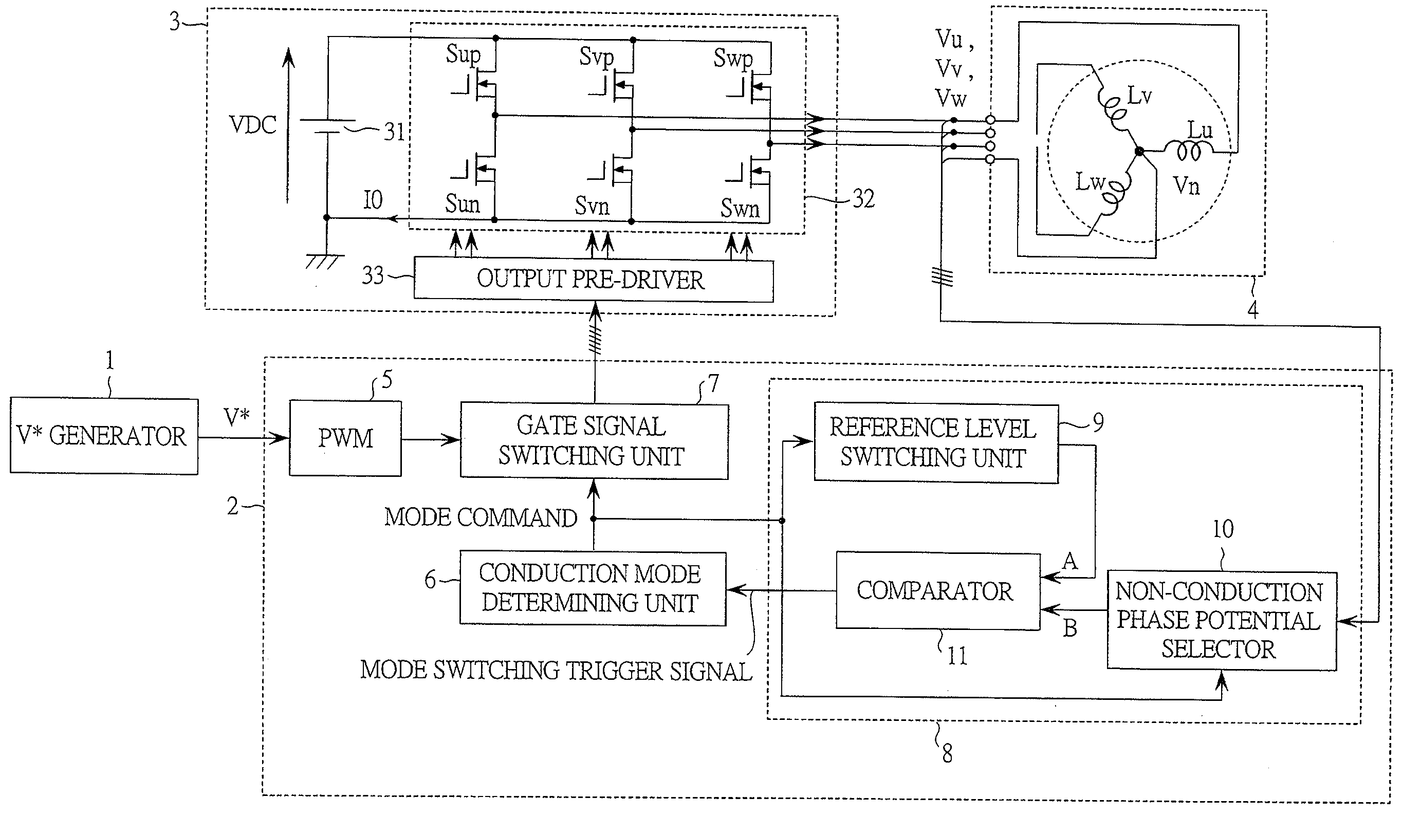
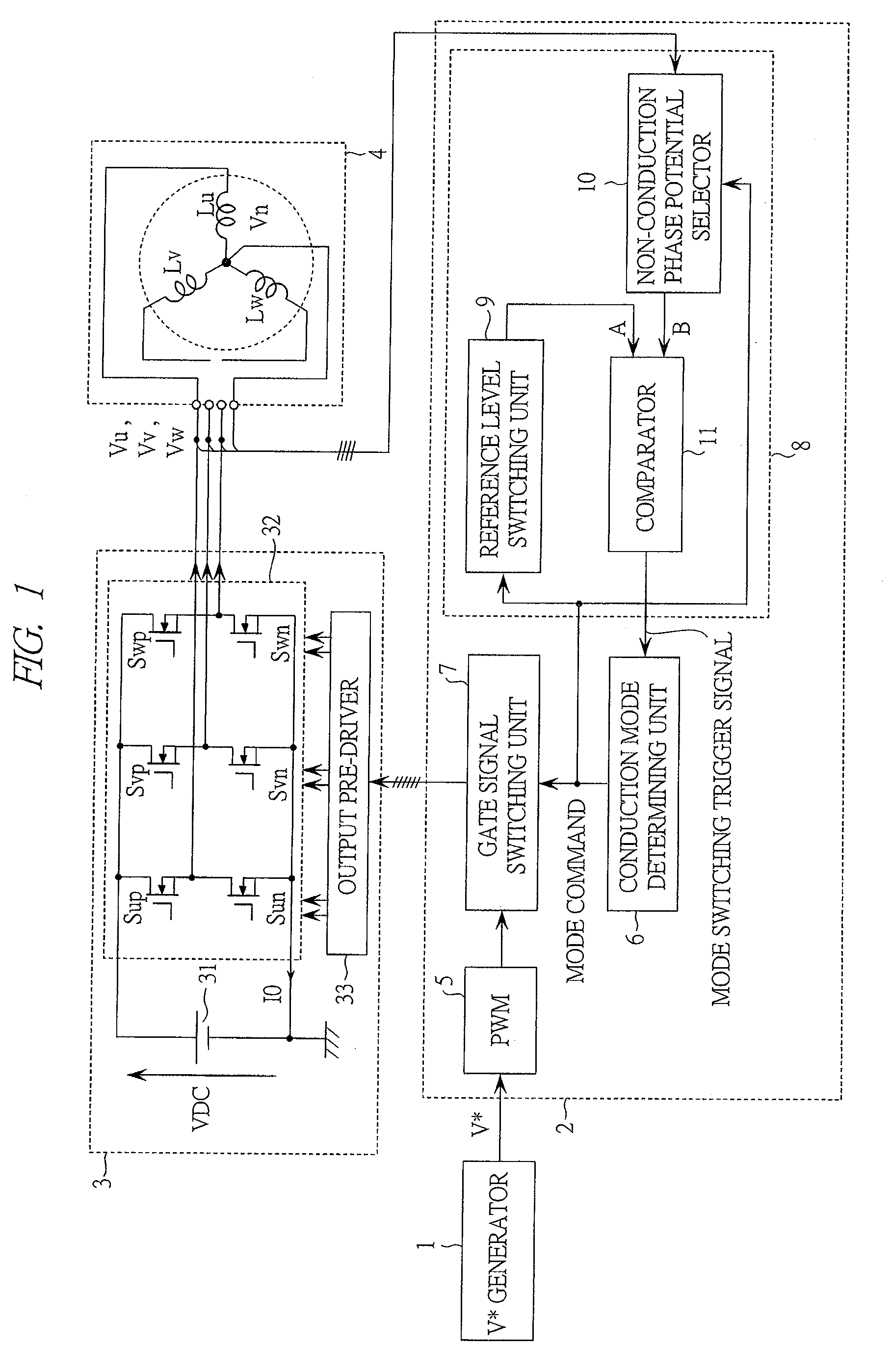
[0057]FIG. 1 is a block diagram showing a configuration of a drive system of a synchronous motor (hereinafter, referred to as a motor drive system) according to the first embodiment of the present invention.
[0058]This motor drive system is intended to drive a permanent magnet motor 4. Roughly classified, the motor drive system is configured to include a V* generator 1, a controller 2, an inverter 3 and the permanent magnet motor 4 to be driven.
[0059]The V* generator is a circuit for generating V* which is an application voltage command of the permanent magnet motor 4. The V* generator 1 is a controller located at an upper level of the controller 2. For example, when the current of the permanent magnet motor 4 is to be controlled, an output of the V* generator 1 can be considered as an output of a current controller. The voltage corresponding to the application voltage command V* is subjected to pulse width modulation (PWM) and then applied to the permanent magnet motor 4.
[0060]The c...
second embodiment
[0090]Next, the second embodiment of the present invention will be described with reference to FIG. 9 and FIG. 10.
[0091]FIG. 9 is a block diagram showing the configuration of a motor drive system according to the present embodiment. The difference between the first embodiment and the present embodiment is that the permanent magnet motor 4 and the inverter 3 are replaced with a permanent magnet motor 4A and an inverter 3A.
[0092]The permanent magnet motor 4A is a motor which does not have a terminal of the neutral point potential Vn. Depending on the types of motor, the neutral point potential is hard to extract (for example, the one in which the winding is Δ connection) and the number of terminals has to be reduced as much as possible in consideration of cost like the motor incorporated in a compressor of an air conditioner. The present invention assumes the use in such cases.
[0093]In the inverter 3A, a virtual neutral point generator 34 is connected to an inverter output portion. Th...
third embodiment
[0096]Next, the third embodiment of the present invention will be described.
[0097]FIG. 11 is a block diagram showing the motor drive system according to the third embodiment. The present embodiment differs in that the controller 2 is replaced with a controller 2C.
[0098]The controller 2C of the present embodiment does not detect the terminal voltage of the permanent magnet motor 4, but it reads the neutral point potential Vn of the permanent magnet motor 4 and the virtual neutral point potential Vnc connected to the output of the inverter instead.
[0099]The difference between the controller 2 of the first embodiment and the controller 2C of the present embodiment is in a mode switching trigger generator 8C. The mode switching trigger generator 8C of the present embodiment amplifies the potential difference between the neutral point potential Vn of the permanent magnet motor 4 and the virtual neutral point potential Vnc by a neutral point potential amplifier 10C. The output of the neut...
PUM
 Abstract
Description
Claims
Application Information