Method for detecting initial position of magnetic pole of rotor of built-in permanent magnetic synchronous motor

A permanent magnet synchronous motor, initial position detection technology, applied in the control of generators, electronic commutators, motor generators, etc., can solve the problems of misjudgment of polarity, poor practicability, complex signal processing, etc., and achieve satisfactory identification Accuracy, simple processing method, reliable effect of judging the rotor magnetic pole polarity method

Inactive Publication Date: 2010-05-26
哈尔滨同为电气股份有限公司 +1
View PDF0 Cites 59 Cited by
  • Summary
  • Abstract
  • Description
  • Claims
  • Application Information

AI Technical Summary

Problems solved by technology

[0005] The purpose of the present invention is to solve the problems existing in the existing method for detecting the initial position of the rotor magnetic pole of the built-in permanent magnet synchronous motor based on high-frequency signal injection, such as t...

Method used


Image

  • Method for detecting initial position of magnetic pole of rotor of built-in permanent magnetic synchronous motor
  • Method for detecting initial position of magnetic pole of rotor of built-in permanent magnetic synchronous motor
  • Method for detecting initial position of magnetic pole of rotor of built-in permanent magnetic synchronous motor

Examples


specific Embodiment approach 1

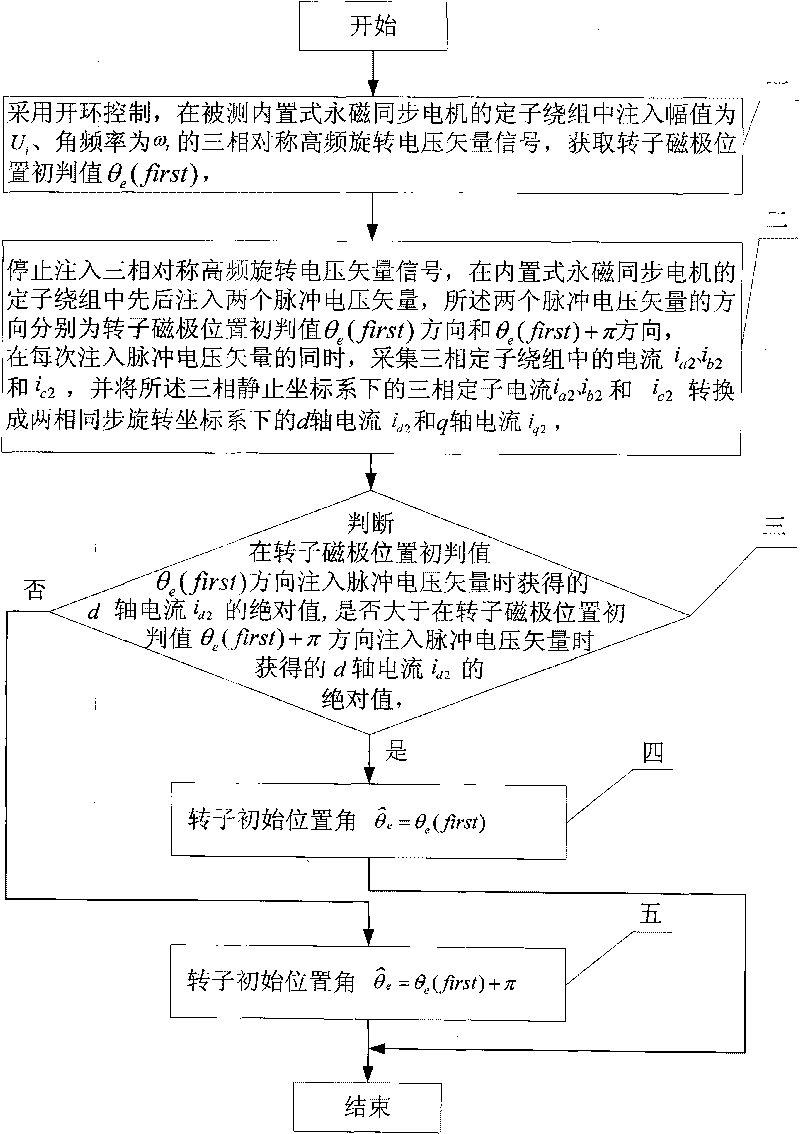
[0018] Specific implementation mode one: the following combination Figure 1 to Figure 5 Describe this implementation mode, this implementation mode comprises the following steps:

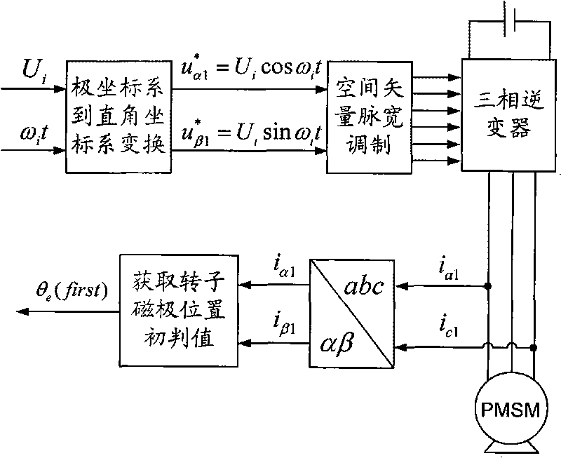
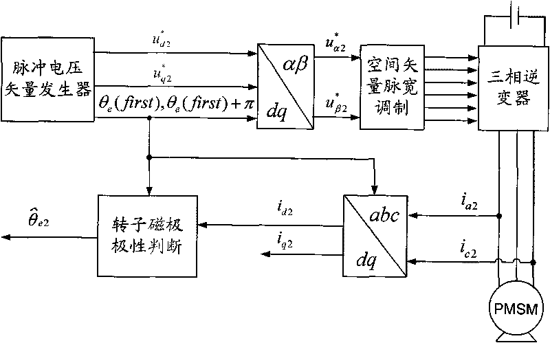
[0019] Step 1: Using open-loop control, inject amplitude U into the stator winding of the built-in permanent magnet synchronous motor under test i , the angular frequency is ω i The three-phase symmetrical high-frequency rotating voltage vector signal, and obtain the initial judgment value of the rotor magnetic pole position θ e (first), the specific method is:

[0020] Step a. Initialize the given position angle of the rotor

[0021] Step b. Transform the three-phase symmetrical high-frequency rotating voltage vector signal from a polar coordinate system to a rectangular coordinate system to obtain a voltage reference value u in a two-phase stationary coordinate system α1 * and u β1 * ,in u β 1 * = ...

specific Embodiment approach 2

[0070] Embodiment 2. The difference between this embodiment and Embodiment 1 is that the angular frequency ω of the three-phase symmetrical high-frequency rotating voltage vector signal i is 500Hz~2kHz, the amplitude U of the high-frequency voltage vector signal i It is 5%-30% of the rated voltage of the built-in permanent magnet synchronous motor to be tested, and the other is the same as the first embodiment.

[0071] The frequency of the injected high-frequency rotating voltage signal is much higher than the rated operating frequency of the interior permanent magnet synchronous motor.

specific Embodiment approach 3

[0072] Specific Embodiment 3. The difference between this embodiment and Embodiment 1 is that the amplitude of the pulse voltage vector injected in the two directions described in step 2 is 20% to 70% of the rated voltage value of the built-in permanent magnet synchronous motor , the pulse width of the pulse voltage vector injected in the two directions is 700 μs-900 μs, and the other is the same as the first embodiment.


PUM

PropertyMeasurementUnit
Pulse widthaaaaaaaaaa

Abstract

The invention provides a method for detecting the initial position of a magnetic pole of a rotor of a built-in permanent magnetic synchronous motor, belongs to the field of motor control, and solves the problems of over-complicated processing, easy occurrence of polarity misjudging, poor practicality and the like existing in the conventional method based on high-frequency signal injection for detecting the initial position of the rotor. The method comprises the following steps: constantly maintaining the stationary state of the rotor; injecting a rotating high-frequency voltage signal into a stator winding; detecting three-phase stator current and converting the three-phase stator current into two-phase static coordinates; acquiring an error signal capable of reflecting position information of the magnetic pole of the rotor through signal processing; adjusting the error signal by using a PI tracker so as to acquire an initial judging value of the position of the magnetic pole of the rotor; and injecting two impulse voltage vectors in opposite directions into the stator winding, comparing values of direct axis current components by detecting the three phase current and converting the rotating coordinates so as to determine the polarity of the magnetic pole, and finally acquiring the initial position angle of the magnetic pole of the rotor of the built-in permanent magnetic synchronous motor.

Description

technical field [0001] The invention relates to a method for detecting the initial position of a rotor magnetic pole of a built-in permanent magnet synchronous motor, belonging to the field of motor control. Background technique [0002] In recent years, the built-in permanent magnet synchronous motor speed control system has gradually become a research hotspot in the field of AC speed control transmission. The reason is that compared with the traditional asynchronous motor, the advantages of the built-in permanent magnet synchronous motor are: high efficiency and energy saving, high power factor, high power density, strong overload capacity, etc. Ideal for drivetrains. According to the different structure of the rotor permanent magnet of the built-in permanent magnet synchronous motor, it can be divided into surface type and built-in type. The permanent magnet of the built-in rotor magnetic circuit structure is located inside the rotor. Due to the asymmetric structure of t...

Claims


Application Information

Patent Timeline
IPC IPC(8): H02P6/16H02P21/32
Inventor 王高林单翌阳杨荣峰于泳汪洋威徐殿国
Owner 哈尔滨同为电气股份有限公司
Why Eureka
Try Eureka