

Clothes processing equipment
A kind of clothing processing equipment and equipment technology, applied in other washing machines, textiles and papermaking, household appliances, etc., can solve the problems of increasing consumer burden and reducing consumer satisfaction, and achieve reasonable connection structure design, stable connection, and convenient location The effect of adjustment
- Summary
- Abstract
- Description
- Claims
- Application Information
AI Technical Summary
Problems solved by technology
Method used
Image

Examples
Embodiment 1
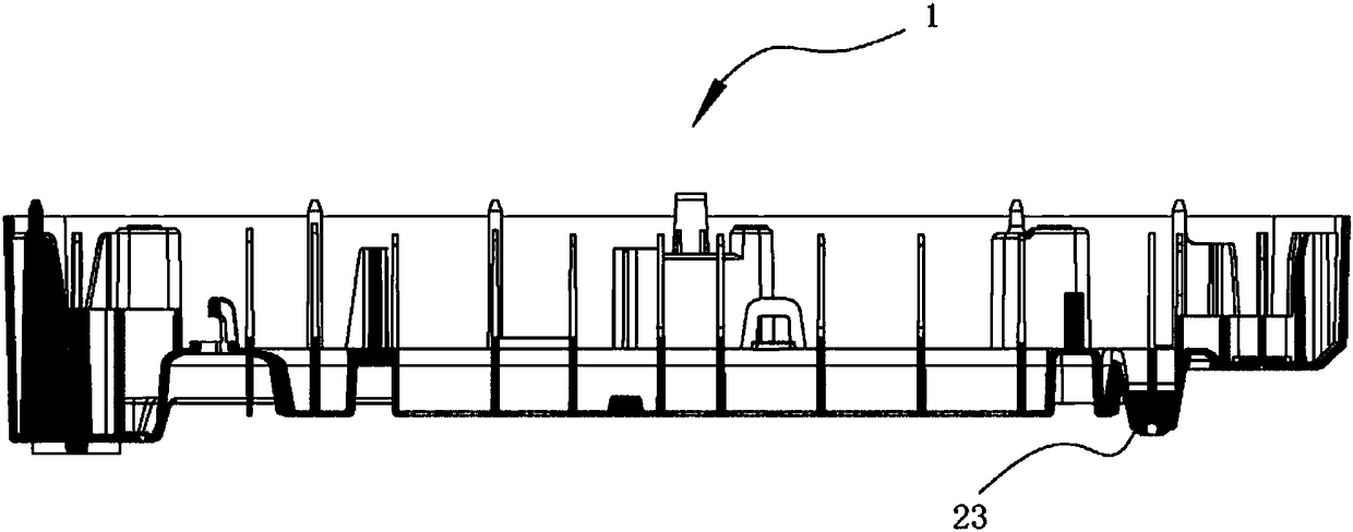
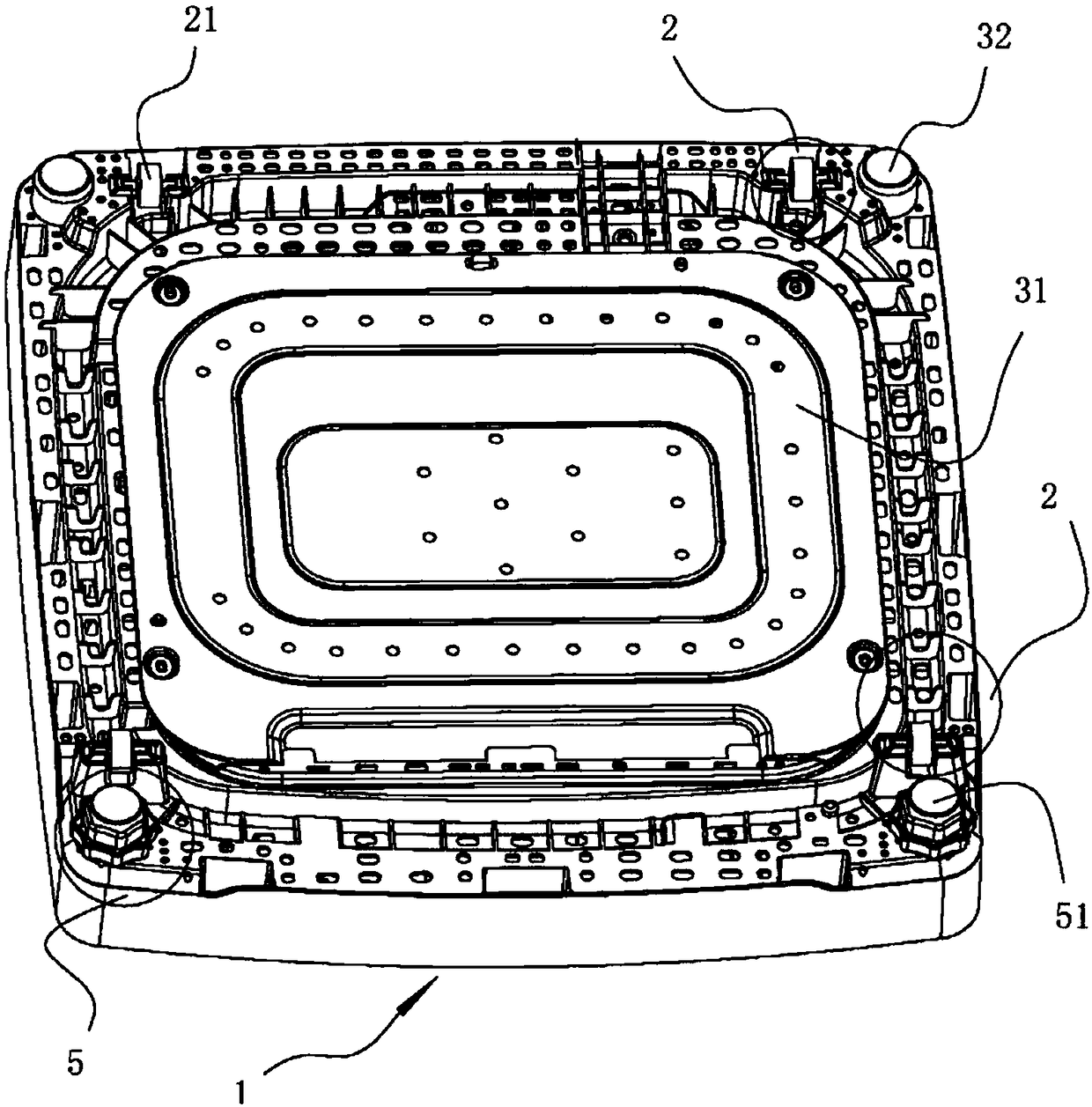
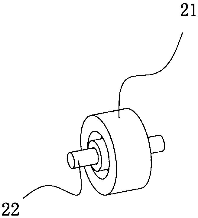
[0070] Such as figure 1 picture, figure 2 , image 3 As shown, the laundry treatment device described in this embodiment includes a base 1 arranged at the bottom of the device; the base 1 includes a moving mechanism 2 for moving the device, so that the device can move under the action of external force. The moving mechanism 2 includes wheels 21 arranged on the base 1 .
[0071] Further, the number of moving mechanisms 2 in this embodiment is four, and the four moving mechanisms 2 are respectively arranged on four corners of the base 1 . Moreover, the distance between the moving mechanisms 2 in front of the equipment is greater than the distance between the moving mechanisms 2 in the rear of the equipment. Since the moving mechanism 2 also plays a supporting and load-bearing role when the equipment is not moving, this design makes the position of the center of gravity at the rear of the equipment more concentrated, which is beneficial to the stability of the equipment. And...
Embodiment 2
[0076] Such as Figure 4 , Figure 5 , Figure 6 As shown, the difference between the laundry treatment device described in this embodiment and the above embodiments is that: the base further includes an anti-collision mechanism for protecting the device.
[0077] Further, the anti-collision mechanism in this embodiment includes an anti-collision mechanism for protecting the base 1 and internal components of the device when the device moves. The anti-collision mechanism includes an anti-collision cover 31 arranged at the bottom of the base 1; the position of the base 1 relative to the anti-collision cover is set as a hollow structure 11, which provides the anti-collision cover 31 deformation space.
[0078] Further, the anti-collision mechanism is connected to the base through a connection mechanism. The connection mechanism includes a first connection mechanism that is snapped in / inserted; the first connection mechanism includes a profile 411 provided on one side of the a...
Embodiment 3
[0085] Such as Figure 7 , Figure 8 As shown, the difference between the laundry treatment device in this embodiment and the above embodiments is that the anti-collision mechanism in this embodiment includes a buffer mechanism for preventing the base from directly contacting the ground. The buffer mechanism includes a buffer protrusion 422 arranged on the lower part of the base; the buffer protrusion 422 is arranged close to the moving mechanism 2; the buffer protrusion 422 is arranged on the side of the moving mechanism close to the edge of the base The buffer protrusion 422 is arranged at least on the rear side of the device, and is arranged in a one-to-one correspondence with the moving mechanism arranged on the side opposite to the moving direction. The buffer protrusion 422 is made of elastic material, preferably rubber.
[0086] Further, in this embodiment, a cavity 33 is formed at the connection position between the buffer protrusion 422 and the device. The design of...
PUM
 Abstract
Description
Claims
Application Information