Circuit arrangement

A circuit device and electromagnetic technology, applied in the field of circuit devices, can solve problems such as consumption, and achieve the effect of reducing energy consumption

Active Publication Date: 2017-03-08
DR JOHANNES HEIDENHAIN GMBH
View PDF9 Cites 1 Cited by
  • Summary
  • Abstract
  • Description
  • Claims
  • Application Information

AI Technical Summary

Problems solved by technology

However, such additional sensor lines represent increased effort when laying cables to the drive solution and also represent additional sources of faults

Method used


Image

  • Circuit arrangement
  • Circuit arrangement

Examples


Embodiment Construction

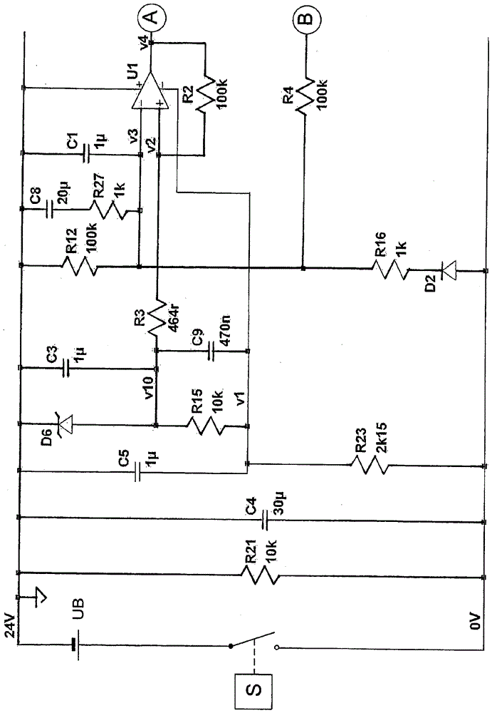
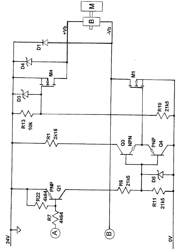
[0019] figure 1 with 2 The complete circuit diagram of the circuit arrangement according to the invention according to the first exemplary embodiment results in an overview. Said circuit diagrams already provide a comprehensive disclosure of the invention to a person skilled in the field of transmission technology, especially for electronic circuits for actuating components of transmission technology. Many of these details are explained below in text, but the subsequent compensation for other details of the circuit arrangement disclosed in the figures should be expressly reserved.

[0020] The holding brake B of the electric motor M is connected to the terminals +Vb, −Vb of the circuit arrangement. Holding brake B releases the shaft of motor M as soon as sufficient voltage is applied via said terminals.

[0021] Therefore, if an operating voltage UB is applied to terminals 0 V, 24 V of the circuit arrangement from the outside, holding brake B is connected to this operating ...


PUM


Abstract

The invention relates to a circuit arrangement. A circuit arrangement is configured to supply an electromagnetic holding brake (B) of an electric motor (M) with an operating voltage (UB) for releasing the holding brake (B), and a voltage that is reduced relative to the operating voltage for holding the holding brake (B) in the released position. In comparison with the prior art the circuit arrangement is characterized in that the operating voltage (UB) is supplied from a control device (S) disposed separately from the electric motor (M) and the holding brake (B). The circuit arrangement is disposed in or on the electric motor (M) or in or on the holding brake (B) and includes a voltage regulator adapted to regulate, independently of the operating voltage (UB), the reduced voltage to a fixed value after the holding brake (B) is released.

Description

technical field [0001] The invention relates to a circuit arrangement for supplying an electromagnetic holding brake of an electric motor with an operating voltage for releasing the holding brake and with a voltage reduced relative to the operating voltage for holding the opened holding brake. Background technique [0002] Electromagnetic holding brakes are used to hold the shaft of an electric motor as long as the electric motor has been taken out of service and is not allowed to move, even with torque delivered from the outside. Such a safe state of the holding brake is the state in which the holding brake is at rest and the axle is clamped. The electromagnetic holding brake is therefore designed in such a way that it is released by means of an electromagnet to which an operating voltage is applied in order to lift the brake pad. If the operating voltage is switched off or fails for other reasons, the brake pad is pressed against the shaft again by means of the mechanical...

Claims


Application Information

Patent Timeline
Patent Type & Authority Applications(China)
IPC IPC(8): H02P3/04H01F7/18
CPCH01F7/18H02P3/04B60T13/743F16D65/186H02P29/00F16D2121/22B60T13/04B60T13/748F16D65/18F16D2121/14Y02T10/72B60L15/2009B60T13/74B60Y2200/91
Inventor M.舍恩利纳C.冯勒苏伊雷
Owner DR JOHANNES HEIDENHAIN GMBH
Why Eureka
Try Eureka