Multilateral bending center die with self-locking and automatic disassembly and assembly functions

An automatic disassembly, self-locking technology, applied in the direction of forming tools, manufacturing tools, metal processing equipment, etc., can solve the problems of poor clamping reliability, unreliable locking, and inability to compensate for accuracy, and achieve reliable clamping of molds. The mold is stable and reliable, and the effect of fast clamping

Pending Publication Date: 2021-12-07
NANJING UNIV OF POSTS & TELECOMM
View PDF17 Cites 1 Cited by
  • Summary
  • Abstract
  • Description
  • Claims
  • Application Information

AI Technical Summary

Problems solved by technology

[0004] As the core component of the CNC bending center, the mold is currently clamped mainly by manual clamping, and the locking methods are mainly "screw locking" and "press plate locking", neither of which can realize automatic clamping
At the same time, poor clamping reliability affects machining accuracy
Since the bending center bears loads in both horizontal and vertical directions during the processing process, the two locking methods will appear as follows during the stress process. image 3 and Figure 4 The mold shown is "turned over", seriously affecting the machining accuracy of the machine tool, and the accuracy cannot be compensated
These two methods rely on external force to lock, and the lock is not reliable.

Method used


Image

  • Multilateral bending center die with self-locking and automatic disassembly and assembly functions
  • Multilateral bending center die with self-locking and automatic disassembly and assembly functions
  • Multilateral bending center die with self-locking and automatic disassembly and assembly functions

Examples


Embodiment 1

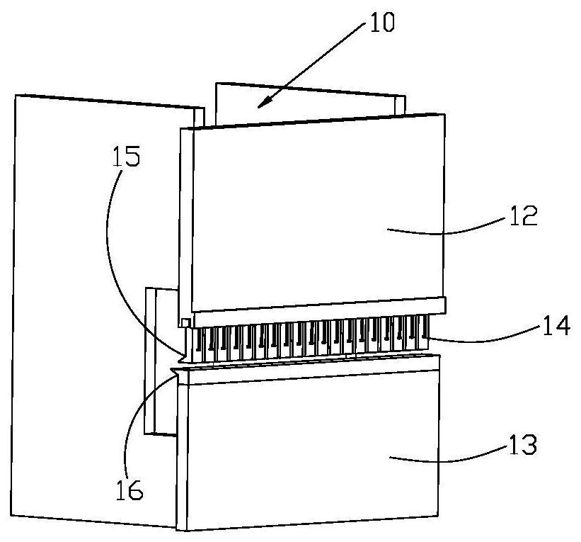
[0096] Such as Figure 5 , Figure 6 and Figure 7 As shown, a multilateral bending center mold with self-locking and automatic disassembly functions includes an upper mold body 20 , a self-locking mechanism 50 and a pressing mechanism 70 .

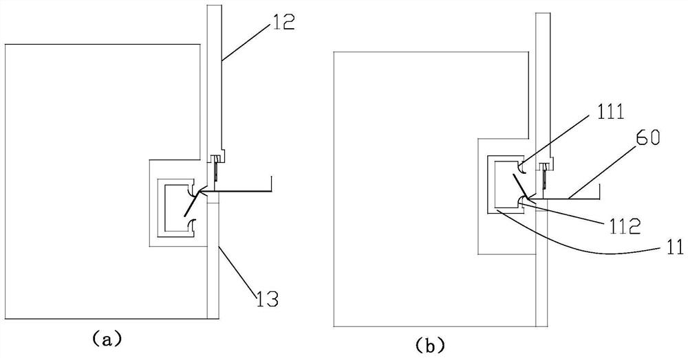
[0097] A tenon 21 is arranged on the top of the upper mold body, and the tenon extends into the inverted U-shaped groove and closely fits with the inner wall of the side leg. The priority between the tenon and the side leg is also set as Figure 24 The adjustment pad 80 is shown. Due to long-term use, the mold is worn out. When the mold is worn out, the pad can be adjusted and the thickness of the pad can be adjusted. At this time, the locking positions of the fixed slanting block and the locking block will change accordingly, and the adjustment of front and rear precision can be realized without scrapping the entire mold body.

[0098] The above-mentioned self-locking mechanism has the following six preferred embodiments.

[0099]...

Embodiment 2

[0144] Such as Figure 14 As shown, the pressing mechanism is a linear drive device 73, one end is hinged to the locking block, and the other end is hinged to the upper mold body.

Embodiment 3

[0146] Such as Figure 15 As shown, the pressing mechanism includes a connecting rod one 71 , a connecting rod two 72 , a linear drive device 73 and a connecting block 74 .

[0147] The connecting block is preferably triangular in shape with three hinge points.

[0148] One end of connecting rod 1 is hinged with the locking block, the other end of connecting rod 1 is hinged with a hinge point of the connecting block (that is, the top hinge point), and the second hinge point of the connecting block (that is, the middle hinge point) It is hinged with the linear drive device 73, and the other end of the linear drive device is hinged on the upper mold body; the third hinge point (ie the bottom hinge point) of the connecting block is hinged on the upper mold body.


PUM


Abstract

The invention discloses a multilateral bending center die with self-locking and automatic disassembly and assembly functions. The multilateral bending center die comprises an upper die body, a self-locking mechanism and a pressing mechanism; the upper die body is detachably installed at the bottom of a cross beam in the bending center, the height of the cross beam can be increased and decreased, and an inverted-U-shaped groove is formed in the bottom of the cross beam and provided with a first side leg and a second side leg; a tenon is arranged at the top of the upper die body, extends into the inverted-U-shaped groove, and is in close fit with the inner wall surface of the first side leg; the self-locking mechanism comprises a fixed inclined block and a locking block; the fixed inclined block is located in the portion, between the tenon and the second side leg, of the inverted-U-shaped groove; the fixed inclined block is provided with a self-locking inclined face; the inclination angle of the self-locking inclined face is alpha, and alpha is smaller than arctan (mu), specifically, mu is the friction coefficient of the self-locking inclined face; and the locking block can be driven by the pressing mechanism to stretch into the inverted-U-shaped groove, so that the tenon is locked in the inverted-U-shaped groove. The self-locking mechanism and the pressing mechanism are adopted, so that double self-locking is achieved, and safety and reliability are achieved.

Description

technical field [0001] The invention relates to the field of numerical control bending, in particular to a multilateral bending center mold with self-locking and automatic disassembly functions. Background technique [0002] At present, the sheet metal processing industry is a typical small batch, multi-variety, and product switching is very frequent. Therefore, frequent mold change operations are required, and domestic manual mold change operations obviously cannot meet the use requirements. The flexibility of equipment requires automatic replacement and clamping of molds, which is the bottleneck that hinders the development of bending centers from automation to flexibility and intelligence, and is also a technical problem that must be overcome. [0003] In recent years, CNC bending centers have developed rapidly in the domestic CNC sheet metal processing equipment market. Thanks to their high processing efficiency and degree of automation, the processing efficiency is 2-3...

Claims


Application Information

Patent Timeline
Patent Type & Authority Applications(China)
IPC IPC(8): B21D37/10B21D37/14B21D5/00
CPCB21D37/10B21D37/14B21D5/004
Inventor 徐丰羽范保杰蒋国平
Owner NANJING UNIV OF POSTS & TELECOMM
Why Eureka
Try Eureka