Air intake device for motorcycle

a technology for air intake and motorcycles, which is applied in the direction of machines/engines, combustion-air/fuel-air treatment, cycles, etc., can solve the problems of insufficient air intake efficiency, adverse effects on rigidity of the motorcycle frame structure, and inability to meet conventional techniques sufficiently, so as to improve engine performance, improve sound quality, and improve air intake efficiency

Active Publication Date: 2017-03-07
KAWASAKI MOTORS LTD
View PDF25 Cites 4 Cited by
  • Summary
  • Abstract
  • Description
  • Claims
  • Application Information

AI Technical Summary

Benefits of technology

[0008]In view of foregoing, the present invention has been devised to provide a motorcycle air intake device in which the air intake efficiency is increased to increase the engine performance and to improve the acoustic quality of sounds of air being introduced.
[0010]According to the present invention, the incoming air taken from the intake air introducing port in the main frame as an engine intake air is supplied from the main intake port in the air cleaner into the air cleaner that is fluid connected with the intake air discharge port in the main frame. At this time, the introducing port of the introducing passage referred to above is defined in a portion of the main frame piece, which is situated rearwardly of the main intake port of the air cleaner, and the intermediate portion of the front portion of the main frame with respect to the motorcycle widthwise direction is formed with the intake air discharge port that is opened rearwardly and fluid connected with the main intake port. Therefore, the introducing passage within the main frame is increased in length and, accordingly, intake air sounds are reduced. Also, since the intake air is also introduced from the sub intake port into the main intake port, the surface area of the intake port is substantially increased. Accordingly, the amount of air sucked into the air cleaner is increased to thereby increase the air intake efficiency, resulting in an increase of the engine performance. Furthermore, since the main frame itself can be used with the conventional parts in the form as they are, the manufacturing cost can be suppressed to a low cost.
[0011]In a preferred embodiment of the present invention, the sub intake port is preferably disposed on a lower side of the main intake port. This structural feature makes it possible to avoid an undesirable intrusion of rain into the sub intake port.
[0013]In a further preferred embodiment of the present invention, the intake duct preferably has a tip end portion fluid connected with the intake air discharge port through a connecting ring made of an elastic material, in which case the connecting ring is provided with a guide portion that protrude downwardly and forwardly from the main intake port to introduce the intake air into the sub intake port. According to this structural feature, merely by mounting the connecting ring, which is made of the elastic material, on the intake duct, the sub intake port can be easily formed by a combination of the guide portion of the connecting ring and the cutout portion in the intake duct. The air cleaner and the main frame are connected together by means of the connecting ring made of the elastic material, and therefore, air tightness is secured, whereby upward and lateral leakage of intake sounds can be reduced.

Problems solved by technology

It has, however, been found that, according to the above mentioned conventional technique, since the air intake port of the air cleaner has a limited open area, the conventional technique is unable to meet sufficiently the recent demands to increase the air intake efficiency and to increase the engine performance.
Although it may be contemplated to increase the air intake efficiency by increasing the open area of the intake port of the air cleaner, the increase of the open area of the intake port of the air cleaner necessitates a concomitant increase of the open area of the intake air discharge port in the motorcycle frame structure that is in communication with the intake port of the air cleaner and, hence, the rigidity of the motorcycle frame structure is adversely affected.

Method used


Image

  • Air intake device for motorcycle
  • Air intake device for motorcycle
  • Air intake device for motorcycle

Examples


Embodiment Construction

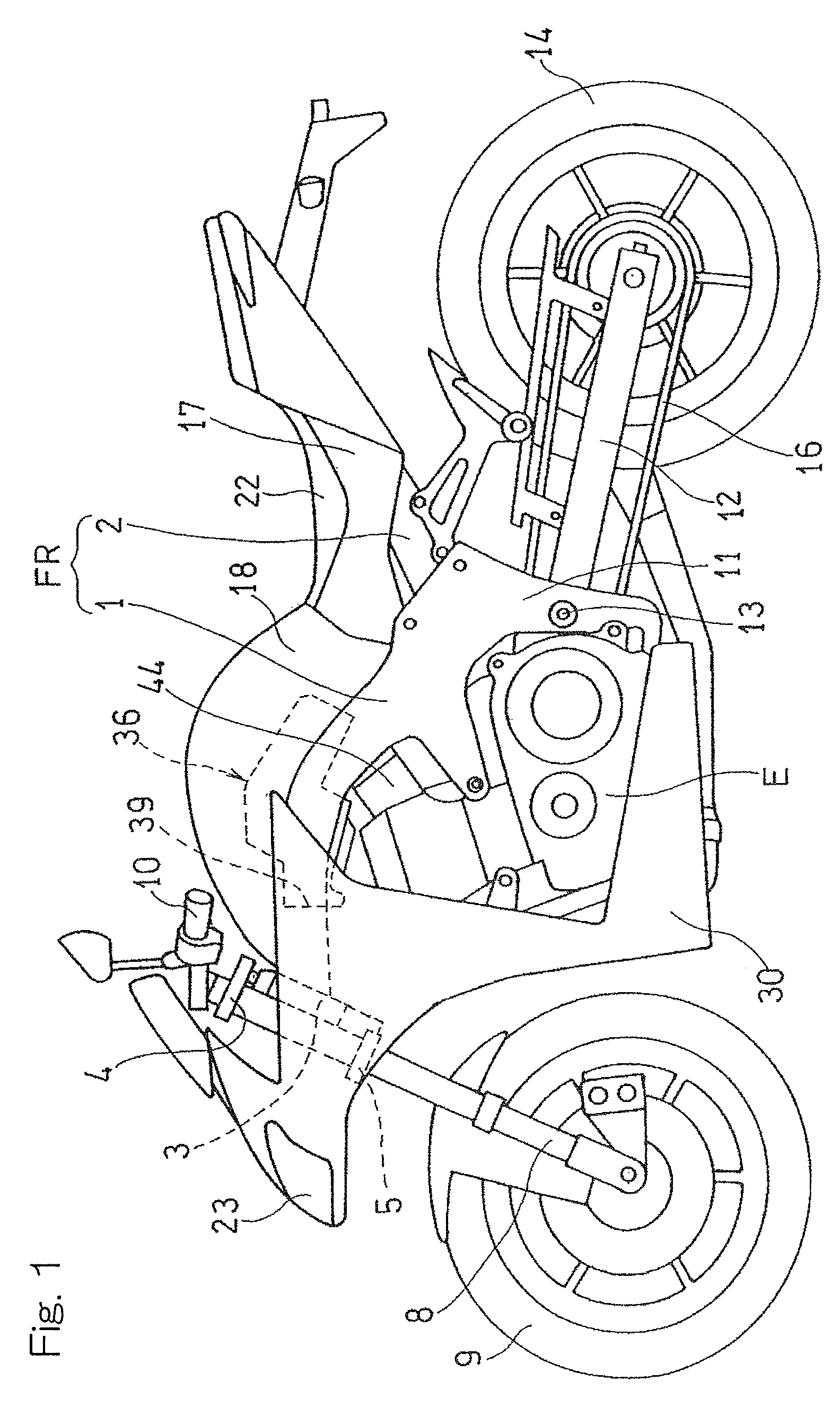
[0023]Hereinafter, a preferred embodiment of the present invention will be described in detail with particular reference to the accompanying drawings. FIG. 1 illustrates a schematic side view of a motorcycle equipped with an air intake device designed in accordance with a preferred embodiment of the present invention. The illustrated motorcycle has a motorcycle frame structure FR which includes a main frame 1, forming a front half unit thereof, and a rear frame 2 connected with a rear portion of the main frame 1 and forming a rear half unit thereof. A head pipe 3 is fitted to a front end portion of the main frame 1; an upper bracket 4 and an under bracket 5 are fitted to a steering shaft (not shown) that is rotatably inserted in the head pipe 3. A front fork 8 is supported by the upper bracket 4 and the under bracket 5, and a front wheel 9 is supported by a lower end portion of the front fork 8. A handlebar 10 is fitted to the upper bracket 4 at an upper end portion of the front for...


PUM

PropertyMeasurementUnit
elasticaaaaaaaaaa
rigidityaaaaaaaaaa
lengthaaaaaaaaaa

Abstract

In an air intake device for motorcycle, an air cleaner having a front end formed with a main intake port is disposed between a pair of left and right main frame pieces forming a main frame. An introducing passage is formed within the main frame for capturing an incoming wind. An intake air introducing port of the introducing passage is provided at a location rearwardly of the main intake port in the main frame piece. An intake air discharge port is defined in an intermediate portion of a front portion of the main frame with respect to a motorcycle widthwise direction so as to open rearwardly and to be fluid connected with the main intake port. A sub intake port is provided in communication with the main intake port so as to introduce an intake air into the main intake port.

Description

CROSS REFERENCE TO THE RELATED APPLICATION[0001]This application is a continuation application, under 35 U.S.C §111(a) of international application No. PCT / JP2014 / 061415, filed Apr. 23, 2014, which claims priority to Japanese patent application No. 2013-105144, filed May 17, 2013, the entire disclosure of which is herein incorporated by reference as a part of this application.BACKGROUND OF THE INVENTION[0002]Field of the Invention[0003]The present invention relates to an air intake device for a motorcycle in which an air intake sound is reduced and an engine performance is improved.[0004]Description of Related Art[0005]The patent document 1 listed below, for example, discloses a conventional air intake device for a motorcycle of a design in which air is introduced from an air intake port into a motorcycle frame structure and then, an air is introduced into an air cleaner main body through an intake port communicated with an intake air discharge port in the motorcycle frame structure...

Claims


Application Information

Patent Timeline
Patent Type & Authority Patents(United States)
IPC IPC(8): B62D61/02F02M35/04F02M35/16B62K11/04F02M35/10
CPCF02M35/162B62K11/04F02M35/048F02M35/10013F02M35/10321F02M35/10124F02M35/10144F02M35/0204F02M35/044Y02T10/12
Inventor TSUBONE, TOSHIYUKI
Owner KAWASAKI MOTORS LTD
Why Eureka
Try Eureka