Supercharge Your Innovation With Domain-Expert AI Agents!

Labyrinth seal

a technology of labyrinth seal and bearing, which is applied in the direction of engine seals, mechanical equipment, engine components, etc., can solve the problems of difficult to obtain adequate maintenance of rotating equipment, easy to wear out lip seals or o-ring shaft seals, and failure, so as to improve the flow of lubricant and enhance sealing performance

Active Publication Date: 2017-03-07
ORION ENGINEERED SEALS
View PDF84 Cites 15 Cited by
  • Summary
  • Abstract
  • Description
  • Claims
  • Application Information

AI Technical Summary

Benefits of technology

The improved labyrinth seal effectively prevents lubricant leakage and contaminant entry, maintaining bearing integrity and equipment reliability by expelling contaminants radially and efficiently returning lubricant to the sump, while minimizing wear and maintaining sealing performance.

Problems solved by technology

Adequate maintenance of rotating equipment is difficult to obtain because of extreme equipment duty cycles, the lessening of service factors, design and the lack of spare rotating equipment in many processing plants.
This is especially true of process pumps, slurry pumps, machine tool spindles, wet end paper machine rolls, aluminum rolling mills and steam quench pumps and other equipment utilizing extreme contamination that can affect lubrication of the bearings of the rotating equipment.
Lip seals or O-ring shaft seals can quickly wear out and fail and are also known to permit excessive amounts of moisture and other contaminants to migrate into the lubricant (oil or grease) reservoir of the operating equipment even before failure had the interface between the rotor and the stator exposed to the contaminates or lubricants at the radial extremity of the seal.

Method used


Image

  • Labyrinth seal
  • Labyrinth seal
  • Labyrinth seal

Examples


Embodiment Construction

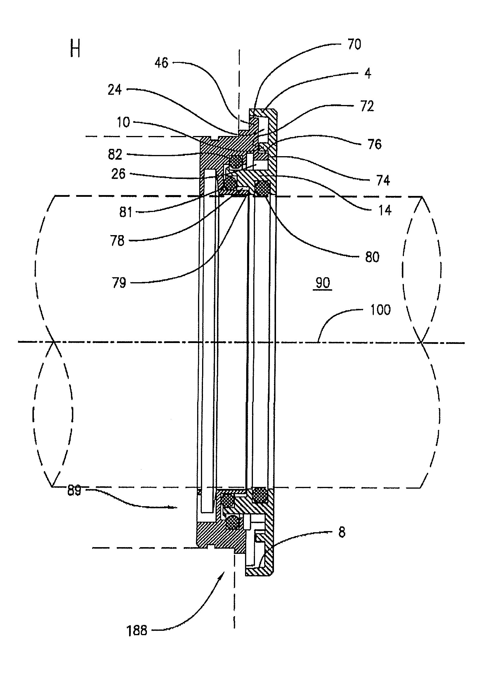
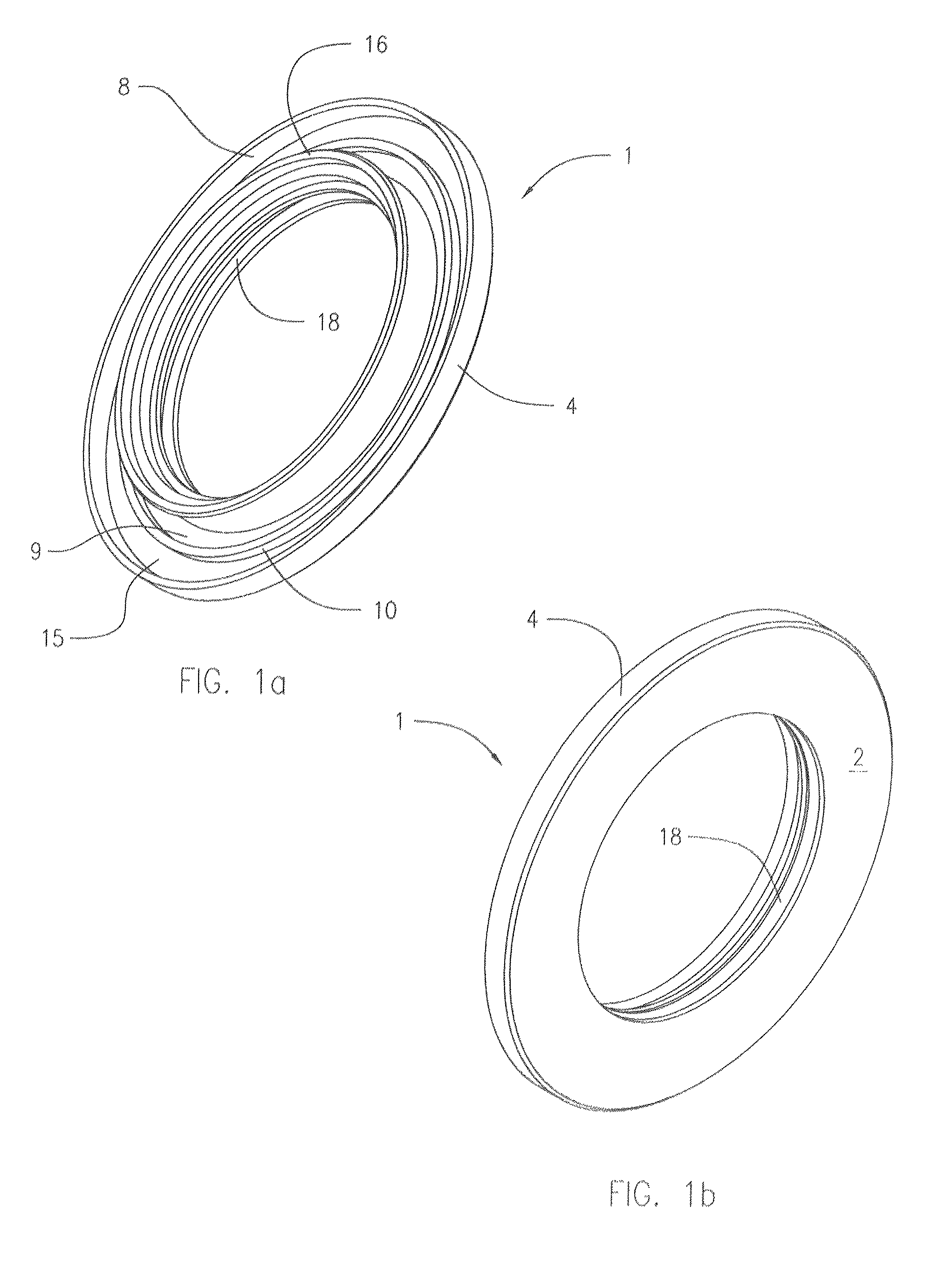
[0030]FIGS. 1a, 1b and 3-5 show a rotor 1 that includes a forward-facing annular wall 2 extending radially from an inner diameter (ID) edge proximate the shaft 90 to an outer diameter (OD) edge, and a first distal annular projection 4 extending rearwardly from the forward wall 2 to a distal end 6. The annular distal projection 4 has an inner annular surface 8 that tapers outwardly and rearwardly at angle θ relative to the axial reference line. The inner annular surface 8 is typically a machined, frustoconical-shaped surface having an acute angle θ of at least 1°, more typically at least 2°, more so typically at least 3°, and up to 45°, typically up to 15°, more typically up to 10°, and more so typically up to 5°.

[0031]A second intermediate annular projection 10 extends to a distal end 12 having a surface substantially perpendicular to an axial reference line 100, and has an inner annular surface 13 that extends substantially parallel to the axial reference line 100. The second inter...


PUM


Abstract

A labyrinth seal including a stator and a non-contacting rotor, and annular elastomeric seals. The confronting surfaces of the stator and rotor define at least one interface passage, including a radially-outermost annular interface passage between an annular, outermost, radially-extending projection of the stator and an annular rearwardly-extending distal projection of the rotor that overlaps the radially-extending projection of the stator, the radially-outermost annular interface passage tapering outwardly and rearwardly at an acute angle relative to an axial reference line. The annular elastomeric seals are stationary with the stator during dynamic operation of the rotor, and are not contacted by a surface of the rotor during dynamic operation. The interface can also have two radially-disposed exclusion chambers, the outer exclusion chamber being defined in part by a radially-inboard projection of the rotor. The stator can have a projection providing a contact avoidance interface position inboard of at least two contaminant-excluding interfaces.

Description

CROSS-REFERENCE TO RELATED APPLICATIONS[0001]This application is a continuation-in-part application of PCT International Application PCT / US2013 / 025505, filed Feb. 11, 2013 (pending), which claims the benefit of U.S. provisional application 61 / 597,587, filed Feb. 10, 2012, the disclosures of which are incorporated herein by reference in their entirety.TECHNICAL FIELD[0002]The present invention relates generally to a shaft-sealing and bearing protecting labyrinth seal for a shaft-driven rotating equipment.BACKGROUND OF THE INVENTION[0003]Adequate maintenance of rotating equipment is difficult to obtain because of extreme equipment duty cycles, the lessening of service factors, design and the lack of spare rotating equipment in many processing plants. This is especially true of process pumps, slurry pumps, machine tool spindles, wet end paper machine rolls, aluminum rolling mills and steam quench pumps and other equipment utilizing extreme contamination that can affect lubrication of t...

Claims


Application Information

Patent Timeline
Patent Type & Authority Patents(United States)
IPC IPC(8): F16J15/00F16J15/447F16J15/32
CPCF16J15/002F16J15/3204F16J15/4476F16J15/4472F16J15/32
Inventor JASKOT, RANDALLNEPA, WOODROWBRICKSON, TODD
Owner ORION ENGINEERED SEALS
Features
  • R&D
  • Intellectual Property
  • Life Sciences
  • Materials
  • Tech Scout
  • Unparalleled Data Quality
  • Higher Quality Content
  • 60% Fewer Hallucinations
Learn More