Combustion calorimeter with a decomposition vessel

a technology of combustion calorimeter and decomposition vessel, which is applied in the direction of material heat development, etc., can solve the problems of difficult, even impossible, accuracy in determining the heat that developed, and achieve the effect of greater accuracy in determining

Active Publication Date: 2017-03-07
IKA WERKE
View PDF9 Cites 0 Cited by
  • Summary
  • Abstract
  • Description
  • Claims
  • Application Information

AI Technical Summary

Benefits of technology

[0006]It is therefore the object to create a calorimeter of the type defined above, comprising a decomposition vessel that allows greater accuracy in determining the heat that developed.
[0008]In this way, the heat rising to the top substantially on its own is absorbed accordingly well and almost entirely in the top region having the greater wall thickness, so that fast, and also accurate, measurement of this heat by way of the increase in the temperature is possible. The reason for this is that, due to the greater wall thickness, the higher thermal capacity of the composition vessel is located in this top region. For uniform conveyance of the heat into the region having the greater wall thickness, it is favorable for the increase in the wall thickness to be steady, which is to say not to be stepped or sudden. It is advantageous for good propagation and conduction of the heat, with good measurability at the same time, if the cross-section of the decomposition vessel is circular both in the bottom region and in the top region thereof, on the inside as well as on the outside. All wall regions thus have the same distance from a central heat source and can be heated accordingly uniformly.
[0009]According to a particularly expedient embodiment of the invention that is essential, the upper sealing wall may be included in the increase in the wall thickness of the side walls, and the at least one temperature sensor may be arranged and inserted in this top sealing wall forming a thickened wall section as compared to the side walls. As a result, the effect of the heat rising to the top in a region having higher thermal capacity is continued into the top sealing wall, where expediently a temperature sensor can be accommodated well.
[0015]A modified embodiment of the invention may provide for the top wall region and / or the top sealing wall of the decomposition vessel to be subsequently connected, in particular detachably or non-detachably, to the lower-lying region or regions of the side wall. This is favorable in terms of producing this decomposition vessel in the shape thereof having an increasing wall thickness.
[0017]The bottom wall region of the decomposition vessel can surround the access opening for a sample holder and for sample charging and can be detachably attached to a mounting arranged in the housing using a screw closure or bayonet catch. The decomposition vessel can thus be easily detached from the usage position thereof and a sample holder can then be appropriate charged. This holder can optionally be installed in the housing, so that the decomposition container can be placed over it and then fastened thereon.
[0019]Especially when combining individual or several of the features and measures described above, a combustion calorimeter comprising a decomposition vessel is achieved, with the aid of which the heat that developed during a combustion process and was absorbed by the decomposition vessel can be determined as accurately as possible, in particular if a dry or waterless calorimeter is involved.

Problems solved by technology

The problem here is that the absorbed heat is to be determined as precisely as possible, or as accurately as possible, which is done by way of the increase in the temperature of the decomposition vessel.
This may make the accuracy of determining the heat that developed more difficult, or even impossible.

Method used


Image

  • Combustion calorimeter with a decomposition vessel
  • Combustion calorimeter with a decomposition vessel

Examples


Embodiment Construction

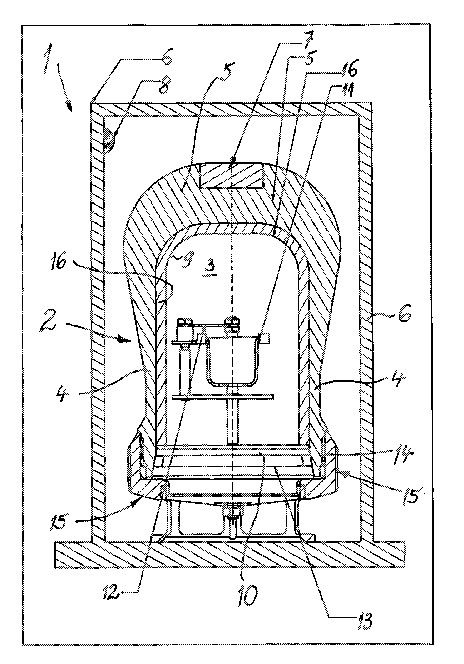
[0022]A combustion calorimeter of the type and having the mode of operation disclosed in DE 43 14 454 C1, denoted in the overall by reference numeral 1, comprises a decomposition vessel, which in the overall is denoted by reference numeral 2 and the interior space 3 of which is designed as a substantially cylindrical reaction chamber by way of side walls 4 and a top sealing wall 5 and is tightly sealed in the usage position.

[0023]The decomposition vessel 2 is replaceably arranged in a housing 6 and comprises a temperature sensor 7 for measuring the temperature 7 of the decomposition vessel 2.

[0024]On the inside of the wall region of the housing 6, at least one second temperature sensor 8 is apparent, which can be connected, for example, to a temperature control device for the decomposition vessel and / or to a computing or control device, which is not shown in detail.

[0025]In the usage position, the longitudinal center axis of the decomposition vessel 2 is oriented vertically in the h...


PUM

PropertyMeasurementUnit
temperatureaaaaaaaaaa
thicknessaaaaaaaaaa
thermal capacityaaaaaaaaaa

Abstract

A combustion calorimeter (1) has a housing (6) and therein a detachably mounted decomposition vessel (2) with sample holder (11) and ignition apparatus (12) in its reaction chamber (3). The wall (4) of the decomposition vessel (2) and also the upper decomposition wall (5) here have in the vertical use position a wall thickness that increases from the bottom to the top in order to conduct the heat generated in a combustion process if possible into the upper region of the decomposition vessel (2), where also at least one temperature sensor (7) can be arranged. Owing to the increase in thickness of the delimitation of the internal or reaction space (3), the heat can be distributed therein more favorably.

Description

CROSS-REFERENCE TO RELATED APPLICATIONS[0001]This application claims priority from PCT / EP2012 / 001704, filed Apr. 19, 2012, which claims priority from DE 10 2011 101 733.3, filed May 17, 2011, which are hereby incorporated by reference herein in their entireties.BACKGROUND OF THE INVENTION[0002]The invention relates to a combustion calorimeter comprising a decomposition vessel, the interior space of which is designed in particular as a cylindrical reaction chamber by way of side walls and a top sealing wall and can be tightly sealed, wherein the decomposition vessel is replaceably arranged in a housing and comprises at least one temperature sensor for measuring the temperature of the decomposition vessel, wherein at least one second temperature sensor is located on the inside of the wall region of the housing, and wherein the decomposition vessel is located in a substantially vertical orientation in the housing in the usage position.[0003]Such a combustion calorimeter comprising a de...

Claims


Application Information

Patent Timeline
Patent Type & Authority Patents(United States)
IPC IPC(8): G01N25/42G01N25/22G01N25/26
CPCG01N25/22G01N25/26
Inventor PINHACK, HUBERT
Owner IKA WERKE
Why Eureka
Try Eureka