
Extrapolation method for the angle-of-rotation position

a technology of rotational position and extrapolation method, which is applied in the direction of galvano-magnetic hall-effect devices, electric control, instruments, etc., can solve the problems of not allowing any improvement beyond the resolution limits, and the maximum resolution of this configuration is not sufficient for modern methods, so as to achieve greater accuracy in determining the crank angle, the effect of improving the resolution of the angle-of-rotation position and/or the crank angl

Inactive Publication Date: 2005-09-29
ROBERT BOSCH GMBH
View PDF5 Cites 30 Cited by
  • Summary
  • Abstract
  • Description
  • Claims
  • Application Information

AI Technical Summary

Benefits of technology

The present invention is related to a device for accurately determining the angle-of-rotation position of a shaft of an internal combustion engine, particularly the crank angle of a crankshaft. The device uses a sensor wheel rotating with the shaft and a detection device to determine information about the increments of rotation and running times of the shaft. The device also has a memory to store the information and a logic circuit to determine the angle-of-rotation position in the time period between two signals by extrapolation of the detected angle-of-rotation position, taking into account at least one angular velocity and / or change in angular velocity extrapolated from the stored information. The invention improves the accuracy of angle-of-rotation position determination even in highly dynamic changes in rotational speed.

Problems solved by technology

However, the maximum possible resolution with this configuration is not sufficient for modern methods in which the crank angle is used as a processing parameter.
However, this reliable method does not allow any improvement beyond the limits of resolution due to the design.

Method used


Image

  • Extrapolation method for the angle-of-rotation position
  • Extrapolation method for the angle-of-rotation position
  • Extrapolation method for the angle-of-rotation position

Examples


Embodiment Construction

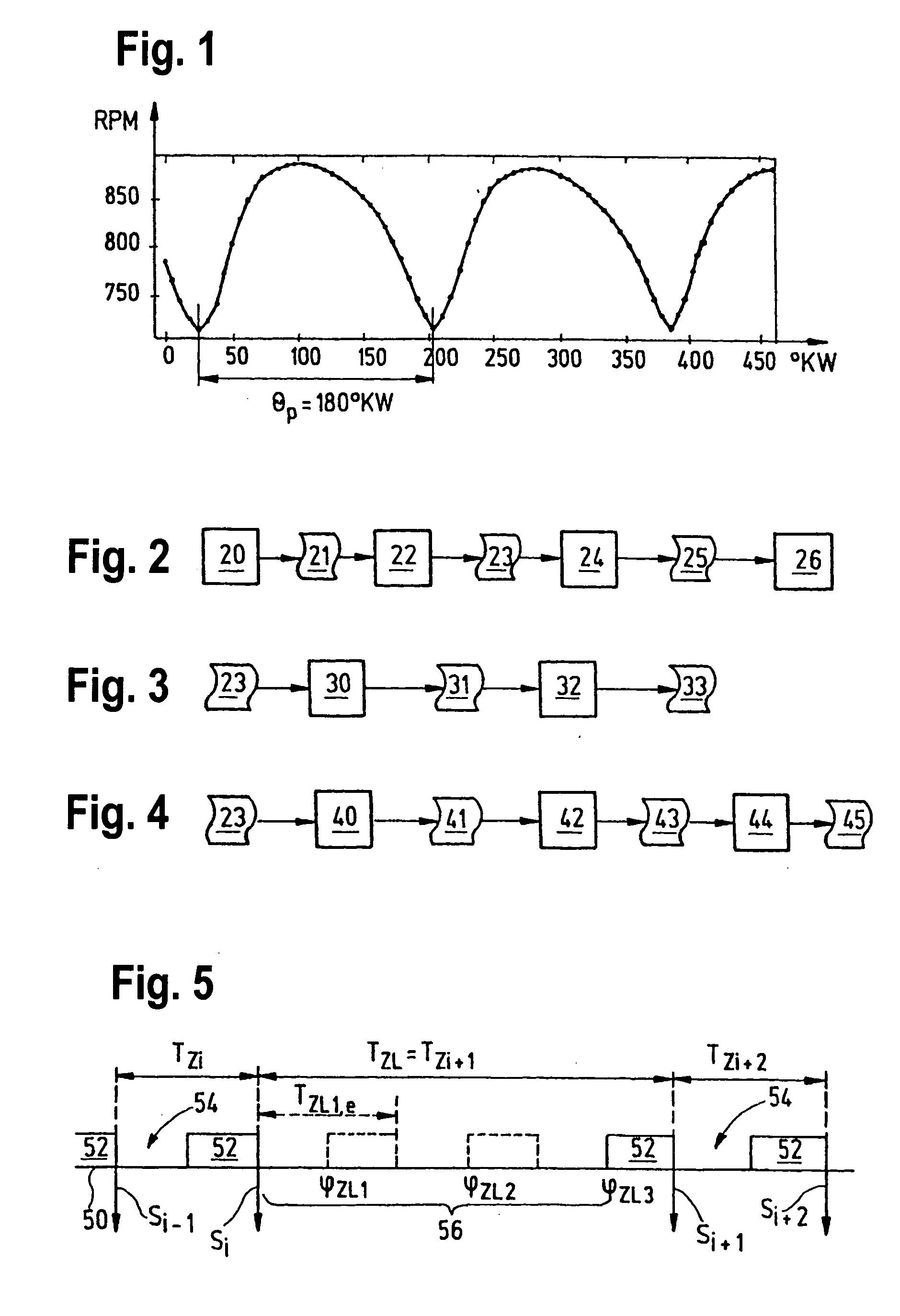
[0020] Instantaneous values for the angular velocity and / or the change in angular velocity are linked with values from past periods for performing the extrapolation. A period, as stated previously, may be defined in various ways. For the exemplary embodiment, the firing interval was selected as the period. FIG. 1 shows the curve of the rotational speed of the crankshaft for a four-cycle internal combustion engine having four cylinders. In the diagram shown there, the crank angle °KW is plotted in degrees on the abscissa and the instantaneous rotational speed rpm in revolutions per minute is plotted on the ordinate. The angle ΘP represents the length of the period. In general, this angle ΘP depends on the number of cylinders Z for a four-cycle engine as follows: ΘP=720⁢°⁢ ⁢K⁢ ⁢WZ.

[0021] The number of measured values per period NP is obtained in general as follows, where Δφ represents the crank angle between two tooth signals: NP=ΘPΔ⁢ ⁢φ.

[0022] The general sequence of determining th...


PUM


Abstract

A method is described for determining the angle-of-rotation position (φ) of a shaft of an internal combustion engine, in particular a crank angle (φ) of a crankshaft, information at least about incremental angles of rotation (Δφ) of the shaft and running times (T) for each incremental angle of rotation (Δφ) being detected on the basis of signals which indicate the rotation of the shaft and are spaced with intervals between them, and stored at least temporarily the instantaneous angle-of-rotation position (φ) being determined in the period of time between two signals by extrapolation of the angle-of-rotation position (φ) thus detected, taking into account at least one angular velocity ({overscore (ψ)}) and / or change in angular velocity (Δ{overscore (ψ)}) extrapolated from the stored information. In addition, a corresponding device is also described.

Description

FIELD OF THE INVENTION [0001] The present invention relates to a method for determining the angle-of-rotation position of a shaft of an internal combustion engine, in particular the crank angle of a crankshaft, information at least regarding incremental angles of rotation of the shaft and running times for each incremental angle of rotation being detected and stored at least temporarily on the basis of signals occurring at time intervals, indicating the rotation of the shaft. Furthermore, the present invention relates to a device for determining the angle-of-rotation position of a shaft of an internal combustion engine, in particular the crank angle of a crankshaft. BACKGROUND INFORMATION [0002] Methods for determining the angle-of-rotation position of a shaft of an internal combustion engine are known. In the case of a crankshaft in particular, determination of the crank angle is of great importance because important sequences in operation of the internal combustion engine, e.g., f...

Claims


Application Information

Patent Timeline
Patent Type & Authority Applications(United States)
IPC IPC(8): F02B77/08F02D41/00G01B7/14G01D5/244G01D5/245G01M15/00G01M15/06G01P3/481
CPCF02D41/009F02D2041/288G01P3/489G01M15/06G01D5/2451
Inventor DAMITZ, JENSPALMER, JOACHIMFEHRMANN, RUEDIGERSCHUELER, MATTHIASZU SCHWEINSBERG, ALEXANDER SCHENCKENGBER, ARNOLDSTEINERT, THOMAS
Owner ROBERT BOSCH GMBH
Learn More