
Procedure to measure the oxygen storage capability of an emission control system

Active Publication Date: 2010-10-26
ROBERT BOSCH GMBH
View PDF19 Cites 6 Cited by
  • Summary
  • Abstract
  • Description
  • Claims
  • Application Information

AI Technical Summary

Benefits of technology

[0021]It is the task of the invention to create a procedure, which allows for a greater accuracy in determining the oxygen storage capability of an emission control system using a simple configuration.
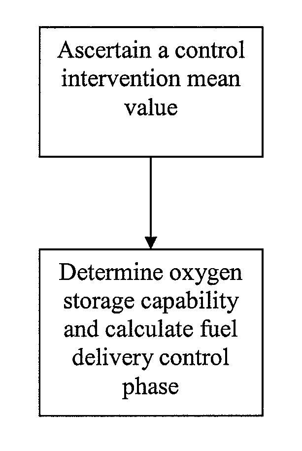
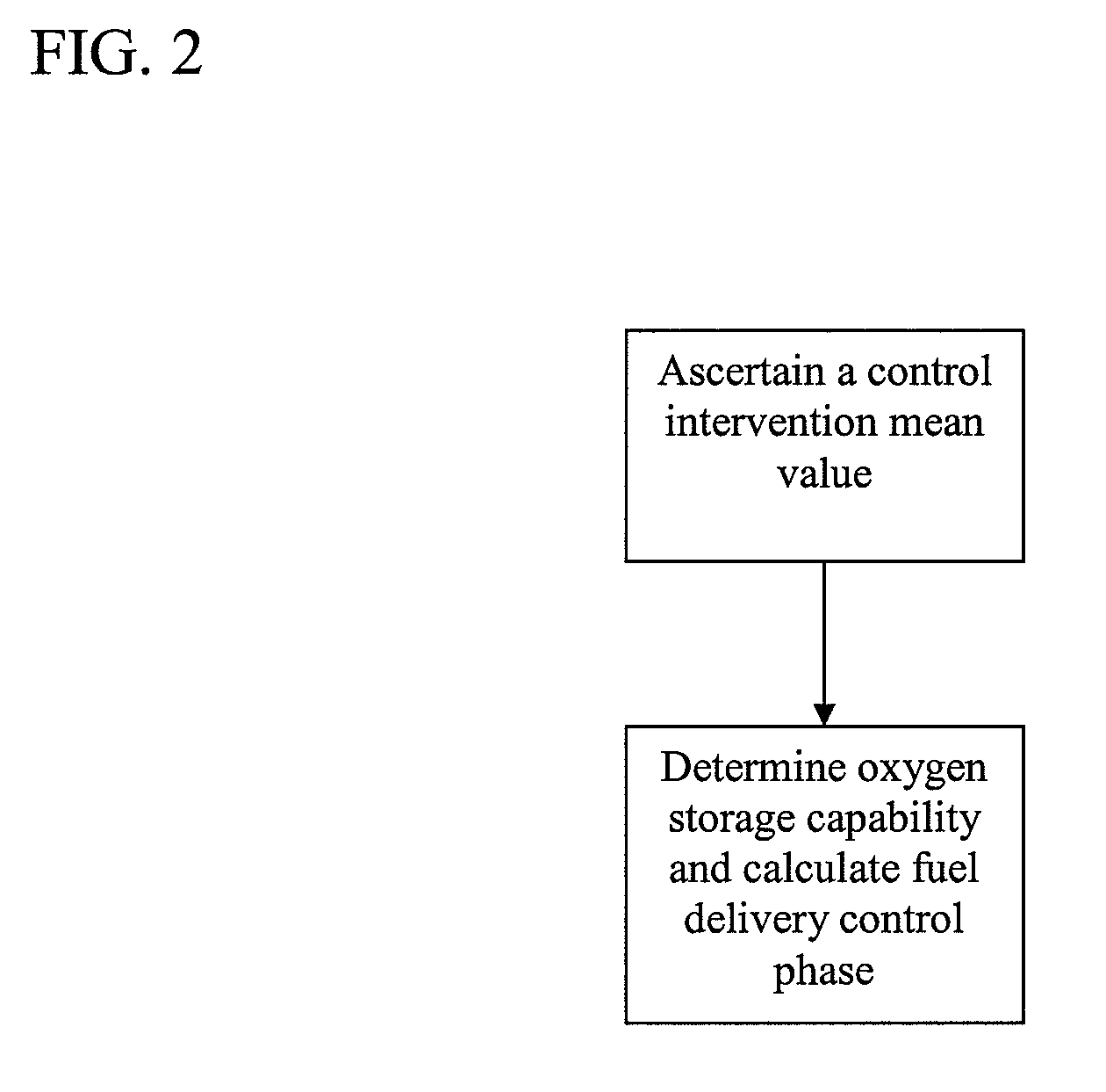
[0022]The task is thereby solved, in that in a period of time before the determination of the oxygen storage capability, the control intervention of the exhaust gas sensor is ascertained, and this mean value is taken into account when calculating the fuel metering during the determination of the oxygen storage capability of the emission control system, or this mean value is used to correct the lambda value used to calculate the amount of oxygen which has been stored. In that during the rich and lean operation of the cycle to determine the oxygen storage capability, the mean value of the control intervention is used for the calculation, pre-control errors are compensated for, as they can, for example, arise by way of dispersion of the injection valves or errors in the acquisition of cylinder fill. If the mean value is used to correct the lambda value, the amount of oxygen stored can be more accurately determined due to the measured air mass. A cost effective discrete-level sensor can be used in front of the emission control system in the procedure according to the invention.
[0023]If the mean value is included multiplicatively in the calculation for fuel amount, the calculation of the correct fuel-delivery control phase from the fuel-delivery control phase determined from the pre-control is especially simple.
[0024]If the averaging and the determination of the oxygen storage capability of the emission control system are initiated only at a steady state operating point of the engine management system, the following events can be achieved: the averaging can result very quickly and furthermore, during the determination of the oxygen storage capability of the internal combustion engine, a largely constant mixture is supplied, whose lambda value is subject to only slight fluctuations.
[0025]The accuracy of the determination of the oxygen storage capability can be additionally improved, in that the averaging and the determination of the oxygen storage capability of the emission control system are initiated at the same operating point of the engine management system, as the errors of the mixture pre-control are generally dependent upon the operating points and consequently can be avoided with this embodiment of the procedure.
[0026]Constant operating ratios of the internal combustion engine can be created, in that a fuel tank ventilation valve is closed before the averaging and the determination of the oxygen storage capability of the emission control system and / or diagnoses with active intervention into the engine management system are blocked out. In so doing the accuracy of the determination of the oxygen storage capability can be improved.

Problems solved by technology

As a result oxygen can no longer be sufficiently provided in the rich phases to purge the exhaust gas of toxic gas components, and the lambda sensor behind the emission control system detects these components to be oxidized.
Furthermore, this lambda sensor detects the oxygen in longer lean phases, which can no longer be stored by the emission control system.
A disadvantage of the procedure described is that the lambda value in front of the emission control system has to be measured with a complex wideband lambda sensor in order to decide on the amount of oxygen introduced or extracted by way of the integration of the product from the actual lambda value and gas quantity stream.
A disadvantage to this procedure is that toxic exhaust gas is released in the lean phases.

Method used


Image

  • Procedure to measure the oxygen storage capability of an emission control system
  • Procedure to measure the oxygen storage capability of an emission control system
  • Procedure to measure the oxygen storage capability of an emission control system

Examples


Embodiment Construction

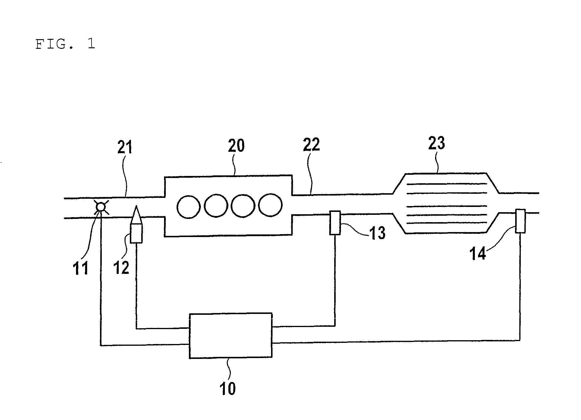
[0029]FIG. 1 shows an internal combustion engine 20, which is controlled by an engine management system 10 and whose exhaust gas is cleaned with an emission control system 23. The internal combustion engine 20 is supplied by way of a delivery air channel 21 with combustion air, whose mass is determined with an air mass gauge 11. The measured air mass is forwarded to the engine management system 10 for the calculation of a fuel amount to be injected. In order to generate the fuel-mixture, the fuel-delivery control phase specified by the engine management system is conducted in the delivery air channel 21 by means of an injection jet 12. Provision is made for an exhaust gas sensor 13 in an exhaust gas tract 22 behind the internal combustion engine 20. With the help of the exhaust gas sensor 13, the engine management system 10 can adjust a lambda value, which is suitable for the subsequent emission control system 23 for achieving an optimal cleaning effect. This exhaust gas sensor 13 i...


PUM


Abstract

The invention concerns a procedure to determine the oxygen storage capability of an emission control system with an exhaust gas sensor with discrete-level ability disposed in front of the emission control system.If in a period of time before the determination of the oxygen storage capability, the control intervention of the exhaust gas sensor is ascertained, and if this mean value is taken into consideration when calculating the fuel-delivery control phase during the determination of the oxygen storage capability of the emission control system, or if this mean value is used to correct the lambda value used to calculate the amount of oxygen stored, an improved measuring accuracy can be achieved while using a cost effective discrete level sensor. In that during the rich or lean operation of the cycle to determine the oxygen storage capability, the mean value of the control intervention is used for the calculation, pre-control errors are compensated for, as they can arise, for example, through dispersion of the injection valves or errors in the acquisition of cylinder fill. If the mean value is used to correct the lambda value, the amount of oxygen stored can be more accurately determined as a result of the measured air mass. In the procedure according to the invention, a cost effective step discrete-level sensor can be used in front of the emission control system.

Description

BACKGROUND[0001]The invention concerns a procedure to determine the oxygen storage capability of an emission control system with an exhaust gas sensor with a discrete-level ability disposed in front of the emission control system. The emission control system can, for example, concern a three-way catalytic converter, which is deployed in a vehicle with a gasoline engine in order to transform toxic exhaust gas components into harmless gases through an oxidation or reduction reaction. The storage capability for oxygen of an emission control system is utilized for the purpose of taking in oxygen in the lean phases and giving it off again in the rich phases. As a result of this even the toxic gas components of the exhaust gas, which are to be oxidized, can be converted. The lambda value one will thus be constantly measured at the outlet of the emission control system. Hence, a stoichiometric balance of the oxidizing and reducing agents occurs. With an increasing deterioration of the emis...

Claims


Application Information

Patent Timeline
IPC IPC(8): G01M15/10
CPCF01N3/0864F01N3/0871F01N11/007F02D41/0295F01N2560/025F01N2560/14F02D41/1454F02D41/1482F02D2200/0816Y02T10/20Y02T10/47Y02T10/12Y02T10/40
Inventor SCHNAIBEL, EBERHARDWOLL, CHRISTOPHHIRSCHMANN, KLAUSHOTZEL, RICHARDLABBE, MAGNUS
Owner ROBERT BOSCH GMBH
Learn More