
Electrical connector

Active Publication Date: 2017-03-07
LOTES
View PDF15 Cites 18 Cited by
  • Summary
  • Abstract
  • Description
  • Claims
  • Application Information

AI Technical Summary

Benefits of technology

The present invention is about an electrical connector that prevents short circuits by using an isolation portion on the tongue of the connector. This isolation portion prevents the grounding elastic sheet of the plug connector from touching the terminal of the socket connector. This design prevents damage to the connectors and ensures safe electrical connections.

Problems solved by technology

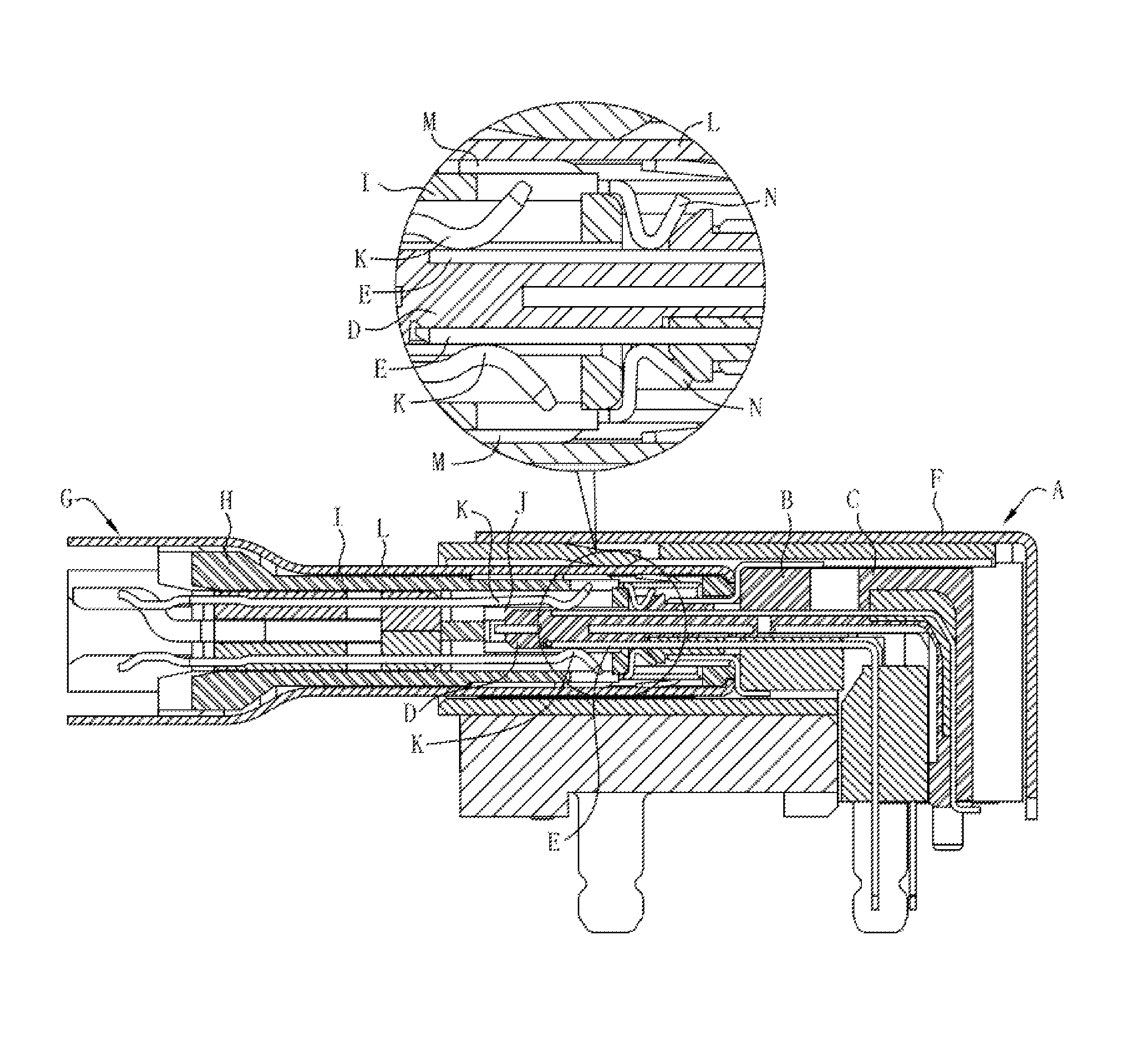
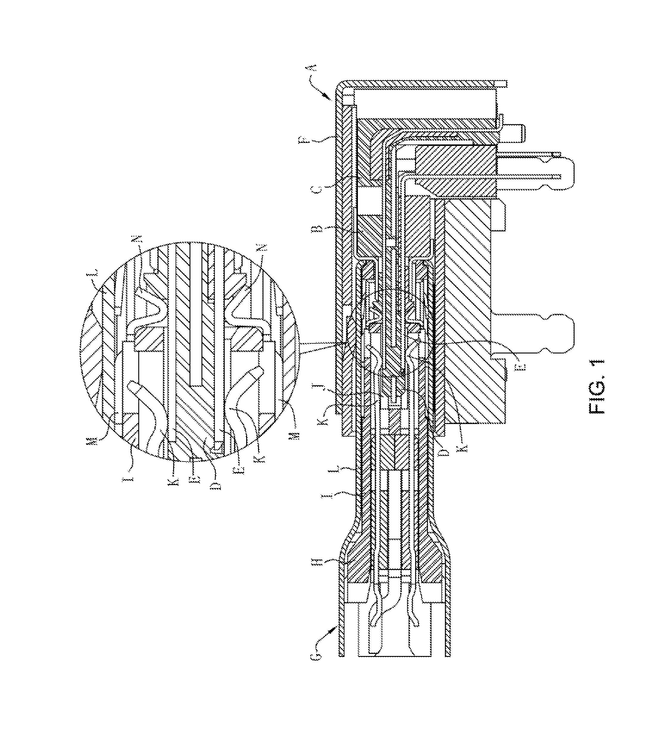
However, after the socket connector A and the plug connector G of the foregoing structure are frequently mated, the elastic sheets N of the plug connector G collide with the tongue D of the socket connector A multiple times, which easily generates a pin collapse phenomenon, and causes the elastic sheets N to be moved backward in the mating cavity J. After pin collapse occurs in the elastic sheets N, when the plug connector G and the socket connector A are mated, the elastic sheets N easily contact the contact portion E of the signal terminal in the socket connector A, thereby causing a short circuit to occur in the socket connector A.
Therefore, a heretofore unaddressed need exists in the art to address the aforementioned deficiencies and inadequacies.

Method used


Image

  • Electrical connector
  • Electrical connector
  • Electrical connector

Examples


Embodiment Construction

[0039]The present invention is more particularly described in the following examples that are intended as illustrative only since numerous modifications and variations therein will be apparent to those skilled in the art. Various embodiments of the invention are now described in detail. Referring to the drawings, like numbers indicate like components throughout the views. As used in the description herein and throughout the claims that follow, the meaning of “a”, “an”, and “the” includes plural reference unless the context clearly dictates otherwise. Also, as used in the description herein and throughout the claims that follow, the meaning of “in” includes “in” and “on” unless the context clearly dictates otherwise. Moreover, titles or subtitles may be used in the specification for the convenience of a reader, which shall have no influence on the scope of the present invention.

[0040]It will be understood that when an element is referred to as being “on” another element, it can be di...


PUM


Abstract

An electrical connector including an insulating body, multiple terminals received in the insulating body, and a contact member. The insulating body includes a base and a tongue extending forward from the base. The tongue has a rear segment and a front segment, and the rear segment is higher than the front segment. Each terminal has a mating portion exposed from the front segment. The front segment has an isolation portion close to the rear segment, and the isolation portion is higher than the mating portion and lower than the rear segment. The contact member is disposed at the rear segment, and used for buckling a grounding elastic sheet of a mating connector during mating. The isolation portion is at least partially located on an insertion path of the grounding elastic sheet.

Description

CROSS-REFERENCE TO RELATED APPLICATIONS[0001]This non-provisional application claims priority to and benefit of, under 35 U.S.C. §119(a), Patent Application No. 201520794974.1 and 201520793583.8 filed in P.R. China on Oct. 15, 2015, the entire contents of which are hereby incorporated by reference.FIELD OF THE INVENTION[0002]The present invention relates generally to an electrical connector, and more particularly to an electrical connector that effectively resolves a short circuit problem.BACKGROUND OF THE INVENTION[0003]The background description provided herein is for the purpose of generally presenting the context of the present invention and is neither expressly nor impliedly admitted as prior art against the present invention. The subject matter discussed in the background of the invention section should not be assumed to be prior art merely as a result of its mention in the background of the invention section. Similarly, a problem mentioned in the background of the invention s...

Claims


Application Information

Patent Timeline
IPC IPC(8): H01R24/60H01R13/6585H01R24/70
CPCH01R13/6585H01R24/70H01R13/6581H01R24/60
Inventor CHANG, WEN CHANGHU, JIN KE
Owner LOTES
Learn More