Electrical connector having a space allowing an elastic connecting member to be escaped

Inactive Publication Date: 2008-03-06
JAPAN AVIATION ELECTRONICS IND LTD
View PDF22 Cites 9 Cited by
  • Summary
  • Abstract
  • Description
  • Claims
  • Application Information

AI Technical Summary

Benefits of technology

[0013]It is therefore an exemplary object of this invention to provide an electrical connector capable of making the pressure contact load stable and further capable of improving the contact reliability.
[0014]It is another exemplary object of this invention to provide an electrical connector capable of preventing a short circuit between contact portions.

Problems solved by technology

Therefore, pressure contact loads of the contacts are unstable and thus there is a problem that the contact reliability is poor.
Further, in the electrical connector of Patent Document 1, there is a problem that when the contacts are compressed, contact portions of the adjacent contacts are brought into contact with each other to be shorted together.
In the IC socket of Patent Document 2, since each contact has the elastic member, the elastic support, and so on, the structure becomes complicated.
Further, in the IC socket of Patent Document 2, the deformation shape of each contact cannot be controlled at the time of compression.
Therefore, pressure contact loads of the contacts are unstable and thus there is a problem that the contact reliability is poor.

Method used


Image

  • Electrical connector having a space allowing an elastic connecting member to be escaped
  • Electrical connector having a space allowing an elastic connecting member to be escaped
  • Electrical connector having a space allowing an elastic connecting member to be escaped

Examples


first exemplary embodiment

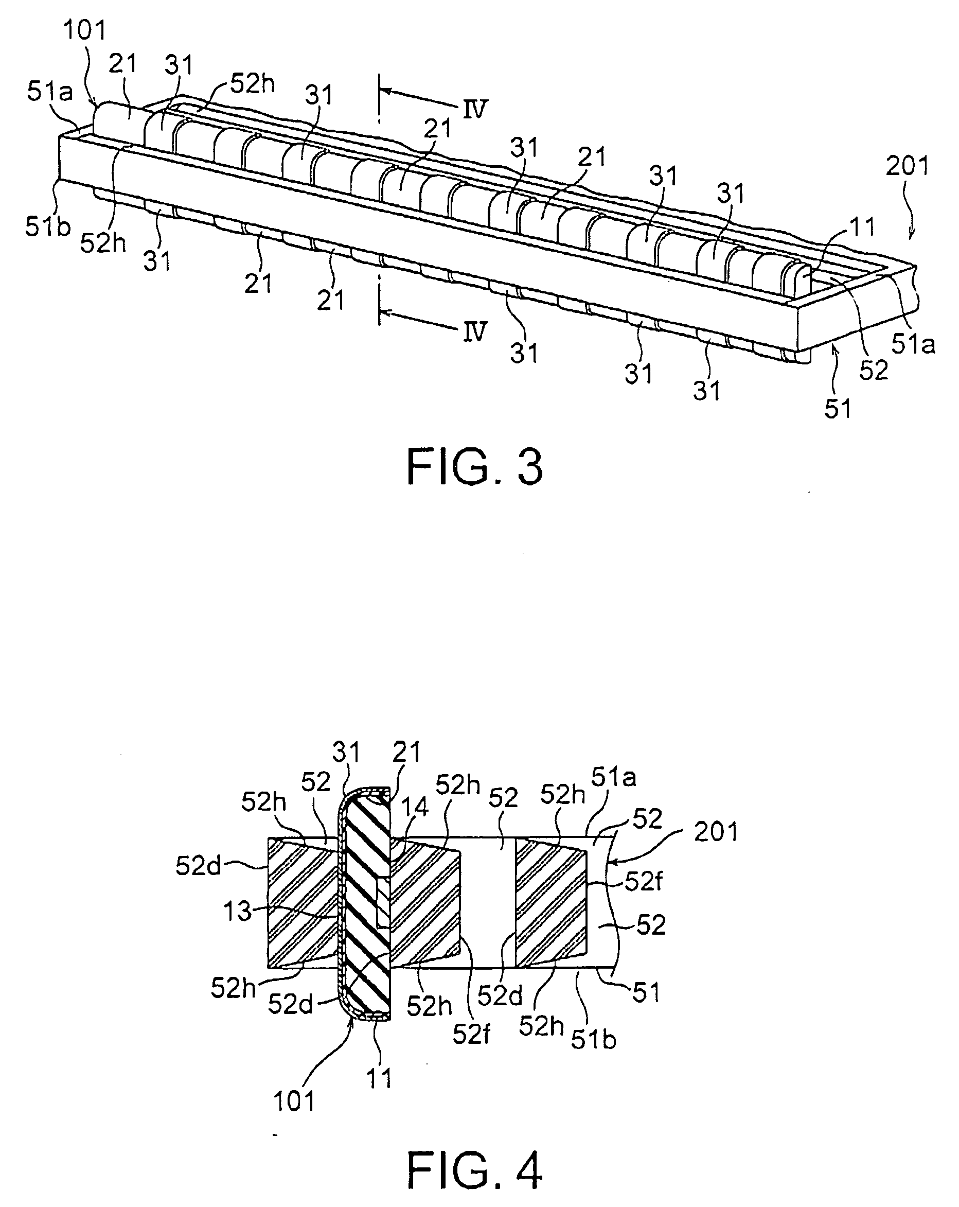
[0063]FIGS. 3 and 4 show the connector 201 as the first exemplary embodiment employing the connecting member 101 described above with reference to FIG. 2.

[0064]The connector 201 includes the connecting member 101 and a plate-shaped holding member (frame member) 51 holding the connecting member 101. The holding member 51 has a plurality of accommodating portions 52 for accommodating a plurality of connecting members 101 individually. Each accommodating portion 52 vertically passes through the holding member 51 including its upper and lower surfaces 51a and 51b opposed to each other.

[0065]As shown in FIG. 4, each accommodating portion 52 includes a first wall 52d, a second wall 52f opposed to the first wall 52d, and a pair of restraining portions 52h. Each restraining portion 52h provides, in the accommodating portion 52, a space (escape portion) for allowing a portion of the connecting member 101 to move in a predetermined direction.

[0066]The first wall 52d is a portion that faces th...

second exemplary embodiment

[0080]FIGS. 6A and 6B show a connector 301 according to a second exemplary embodiment of this invention, wherein the connector 301 employs the connecting members 1 described above with reference to FIG. 1. In the connector 301 of the second exemplary embodiment, the shape of each of accommodating portions 52 of a holding member 51 is changed from that described above in the first exemplary embodiment. The other structure is the same as that of the first exemplary embodiment. Therefore, explanation of those portions other than the accommodating portions 52 is omitted.

[0081]FIG. 6A shows the connector 301 holding the connecting members 1 in three of the accommodating portions 52, respectively.

[0082]Each accommodating portion 52 includes a first wall 52d that faces the base surface 14 of the elastic body 11, a second wall 52f that faces the holding surface 13 of the elastic body 11, and a pair of restraining portions 52j.

[0083]The height of the first wall 52d is set to be greater than...

third exemplary embodiment

[0092]FIGS. 7A and 7B show a connector 401 according to a third exemplary embodiment of this invention, wherein the connector 401 employs the connecting members 1 described above with reference to FIG. 1. In the connector 401 of the third exemplary embodiment, the shape of each of accommodating portions 52 of a holding member 51 is changed from that of the connector 201 described above in the first exemplary embodiment. Therefore, explanation of those portions other than the accommodating portions 52 is omitted.

[0093]Referring to FIG. 7A, each accommodating portion 52 has a first wall 52d that faces the base surface 14 being one side of the connecting member 1, a second wall 52f that faces the holding surface 13 of the elastic body 11, an additional restraining portion 52m projecting from the second wall 52f, and a pair of restraining portions 52n.

[0094]The additional restraining portion 52m has a protruding shape for pushing and deforming the conductors 31 in a predetermined direc...


PUM


Abstract

In an electrical connector for connecting connection objects to each other in a connecting direction, a holding member has an accommodating portion between a first and a second surface to which the connection objects are opposed, respectively, when connected to said electrical connector. A connecting member has elasticity and is placed in the accommodating portion. The holding member includes a first and a second wall which define the accommodating portion therebetween. At least one of the first and the second walls includes a restraining portion defining a space which allows a portion of the connecting member to elastically move in a predetermined direction crossing the connecting direction.

Description

[0001]This application is based upon and claims the benefit of priority from Japanese patent application No. 2006-232742, filed on Aug. 29, 2006, the disclosure of which is incorporated herein in its entirety by reference.BACKGROUND OF THE INVENTION [0002]This invention relates to an electrical connector having a connecting member for connection between a connection object and a mating connection object.[0003]As a related art, Japanese Unexamined Patent Application Publication (JP-A) No. 2002-252044 (Patent Document 1) discloses an electrical connector having contacts adapted to be disposed between two mounting boards and restraining portions serving to restrain inclination of the contacts due to bending thereof, respectively.[0004]In this electrical connector, the contacts made of a conductive elastomer material are elastically compressed to thereby achieve electrical connection between the mounting boards. The restraining portions restrain the inclination of the contacts due to be...

Claims


Application Information

Patent Timeline
IPC IPC(8): H01R4/58
CPCH01R13/2414H01R12/714H01R12/52
Inventor ARAI, KATSUMIMATSUO, SEIYAYONETA, AKANE
Owner JAPAN AVIATION ELECTRONICS IND LTD
Why Eureka
Try Eureka