
Display device

a display device and display technology, applied in the direction of semiconductor devices, organic semiconductor devices, diodes, etc., can solve the problems of defective drive and limited design conditions, and achieve the effect of preventing a short circui

Active Publication Date: 2018-02-01
LG DISPLAY CO LTD
View PDF1 Cites 6 Cited by
  • Summary
  • Abstract
  • Description
  • Claims
  • Application Information

AI Technical Summary

Benefits of technology

The present invention aims to provide a display device that can prevent short circuits between electrodes when a circuit is formed in a limited space of a subpixel. This is particularly useful for high-resolution display panels (e.g. UHD or higher). The technical effect of this invention is to improve the reliability and quality of high-resolution display panels.

Problems solved by technology

Design conditions become limited in a layout in which a circuit is formed within a limited space of a subpixel.
In such a case, a short circuit may occur between electrodes, which may result in a defective drive, and an improvement thereof is required.

Method used


Image

  • Display device
  • Display device
  • Display device

Examples


example embodiment

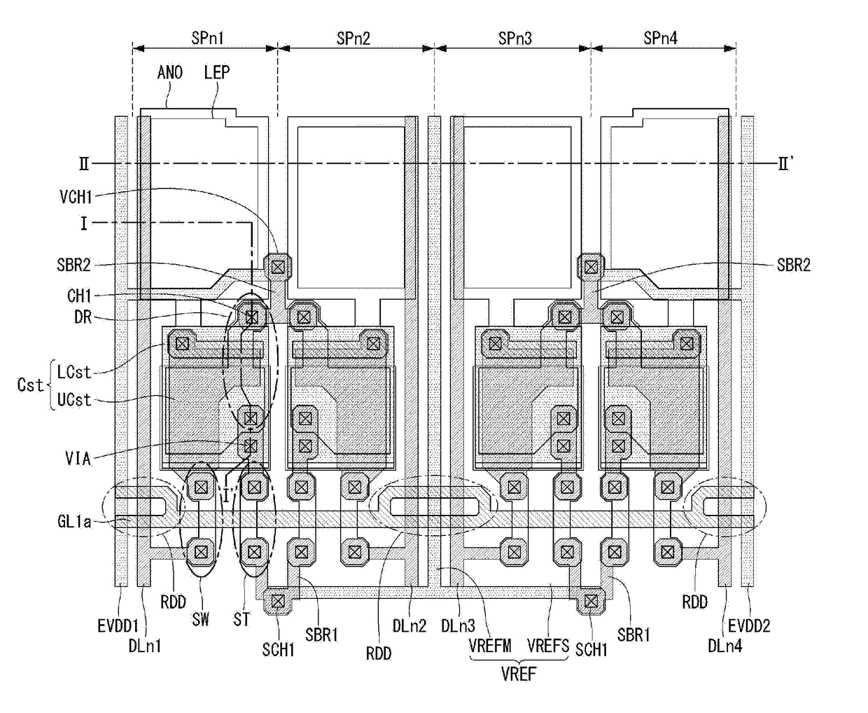
[0050]FIG. 5 is a plan view of a subpixel array according to an example embodiment. FIG. 6 is a cross-sectional view taken along line I-I′ of FIG. 5. FIG. 7 is a cross-sectional view taken along line II-II′ of FIG. 5. FIG. 8 illustrates a branch portion of a scan line.

[0051]With reference to FIG. 5, first to fourth subpixels SPn1 to SPn4 are arranged in a horizontal direction. For example, the first subpixel SPn1 may be a red subpixel R, the second subpixel SPn2 may be a green subpixel G, and the third subpixel SPn3 may be a blue subpixel B. The fourth subpixel SPn4 may be selected as a white subpixel W. In some embodiments, the first to third subpixels SPn1 to SPn3 may form a unit pixel, and three subpixels including the fourth subpixel SPn4 and two subpixels subsequent to the fourth subpixel SPn4 may form a unit pixel. For example, each of RGB, WRG, BWR, and GBW may form a unit pixel. Alternatively, the first to fourth subpixels SPn1 to SPn4 may form a unit pixel, and each of WRGB...


PUM


Abstract

A display device, includes a substrate; first to fourth subpixels sequentially arranged on the substrate; a first power line on a left side of the first subpixel and shared by the first and second subpixels; a sensing line between the second subpixel and the third subpixel and shared by the first to fourth subpixels; a second power line on a right side of the fourth subpixel and shared by the third and fourth subpixels; and a first data line on the left side of the first subpixel, a second data line on a right side of the second subpixel, a third data line on a left side of the third subpixel, and a fourth data line on the right side of the fourth subpixel. The first and second power lines and the sensing line are disposed on a layer different from the first to fourth data lines.

Description

[0001]This application claims the priority benefit of Korean Patent Application No. 10-2016-0097462 filed on Jul. 29, 2016, which is incorporated herein by reference for all purposes as if fully set forth herein.BACKGROUNDTechnical Field[0002]The present disclosure relates to a display device.Discussion of the Related Art[0003]Various types of flat panel displays (FPDs) have been used to replace heavier and larger cathode ray tubes (CRTs). Examples of the flat panel display include a liquid crystal display (LCD), a field emission display (FED), a plasma display panel (PDP), and an organic light emitting diode (OLED) display.[0004]In more detail, an OLED display is a self-emission display device configured to emit light by exciting an organic compound. The OLED display does not require a backlight unit as needed in a liquid crystal display, and thus, has a thin profile, light weight, and a simple manufacturing process. The OLED display can also be manufactured at a low temperature wh...

Claims


Application Information

Patent Timeline
IPC IPC(8): H01L27/32
CPCH01L27/3276H01L27/3258H01L2251/5392H01L27/3272H01L27/322G02F1/1333G02F1/136286G02F1/136295H10K59/131H10K59/1201H10K59/351H10K59/38H10K59/126H10K2102/341H10K71/861H01L27/1244H10K59/1213H10K59/124
Inventor GANG, BYEONGUKSHIM, JONGSIKKIM, HYUNJINKIM, JOONDONG
Owner LG DISPLAY CO LTD
Learn More