Intermediate connector
a technology of intermediate connectors and connectors, which is applied in the direction of elastomeric connecting elements, electrolytic organic production, coupling device connections, etc., can solve the problems of difficult to narrow the pitch of fine conductive patterns, difficult to thin the electrical connector, and difficult to narrow the pitch of conductive thin wires. achieve the effect of preventing a short circui
- Summary
- Abstract
- Description
- Claims
- Application Information
AI Technical Summary
Benefits of technology
Problems solved by technology
Method used
Image
Examples
first embodiment
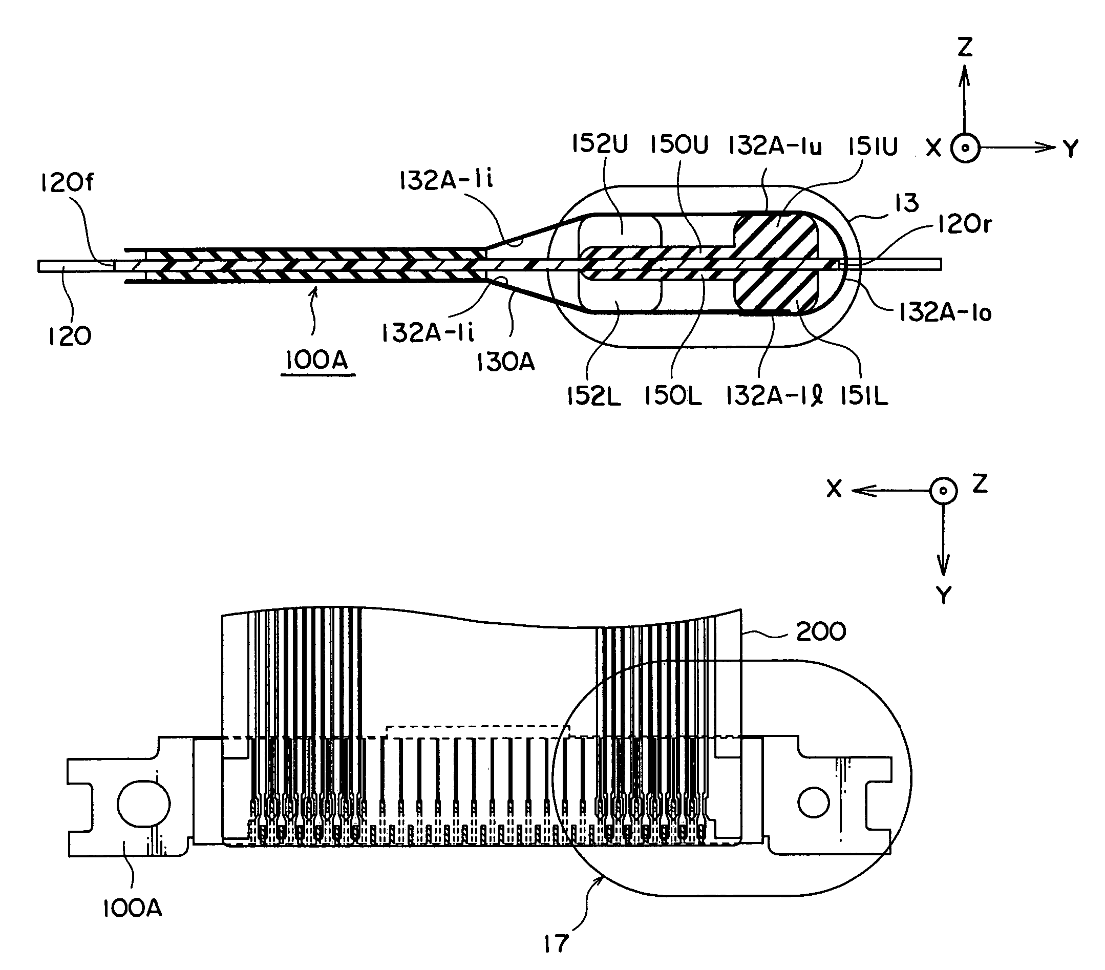
[0066]Referring to FIGS. 10 through 14, the description will proceed to an electrical connector 100A according to this invention. FIG. 10 is a perspective view of the electrical connector 100A. FIG. 11 is a cross sectional view taken on line XI-XI of FIG. 10. FIG. 12 is a cross sectional view taken on line XII-XII of FIG. 10. FIG. 13 is an enlarged view of the electrical connector 100A enclosed in an ellipse 13 in FIG. 11. FIG. 14 is an enlarged view of the electrical connector 100A enclosed in an ellipse 14 in FIG. 12.
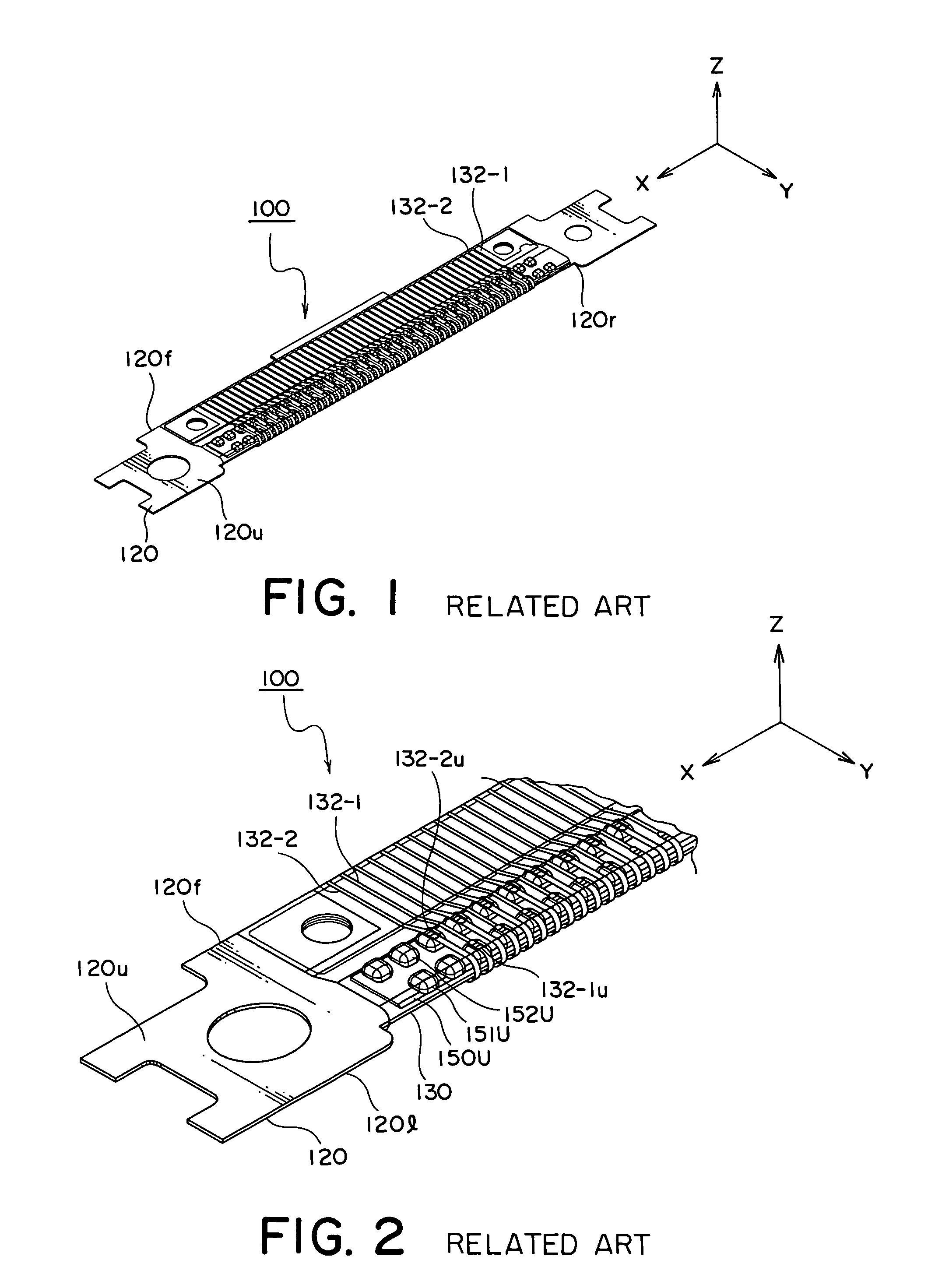
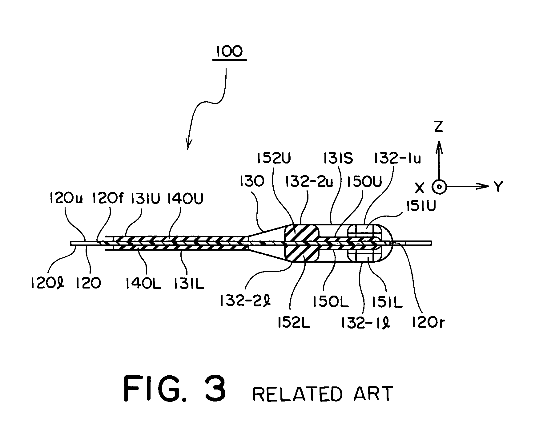
[0067]The illustrated electrical connector 100A is similar in structure to that illustrated in FIGS. 1-3 except that the flexible conductive film is modified from that illustrated in FIGS. 1-3 in the manner which will later be described. The flexible conductive film is therefore depicted at a reference symbol of 130A. Similar reference symbols are attached to those similar to the electrical connector 100 in illustrated in FIGS. 1-3 and description thereof is omitted t...
second embodiment
[0081]In the flexible conductive film 130B of the electrical connector according to this invention, the film conductive pattern 132B is formed not only on the outer surface 131o but also on the inner surface 131i of the flexible insulating film 131, as shown in FIGS. 18A and 18B.
[0082]More specifically, the film conductive pattern 132B consists of a plurality of first and second conductive fine lines 132B-1 and 132B-2 which are arranged along the lateral direction X. In other words, the first and the second conductive fine lines 132B-1 and 132B-2 extend in parallel with each other in the back-and-forth direction Y and are spaced from each other in the lateral direction X at the predetermined line pitch Pl. The first conductive fine lines 132B-1 and the second conductive fine lines 132B-2 are alternatively arranged along the lateral direction X.
[0083]Each of the first conductive fine lines 132B-1 has a first upper electrode pad or contact portion 132B-1u formed above the correspondin...
sixth embodiment
[0113]In the flexible conductive film 130F of the electrical connector according to this invention, the film conductive pattern 132F is formed not only on the outer surface 131o but also on the inner surface 131i of the flexible insulating film 131, as shown in FIGS. 23A and 23B.
[0114]More specifically, the film conductive pattern 132F consists of a plurality of first and second conductive fine lines 132F-1 and 132F-2 which are arranged along the lateral direction X. In other words, the first and the second conductive fine lines 132F-1 and 132F-2 extend in parallel with each other in the back-and-forth direction Y and are spaced from each other in the lateral direction X at the predetermined line pitch Pl. The first conductive fine lines 132F-1 and the second conductive fine lines 132F-2 are alternatively arranged along the lateral direction X. Each of the first and the second conductive fine lines 132F-1 and 132F-2 extends from near the front edge 120f of the plate-like base member...
PUM
 Abstract
Description
Claims
Application Information
 - R&D
- Intellectual Property
- Life Sciences
- Materials
- Tech Scout
- Unparalleled Data Quality
- Higher Quality Content
- 60% Fewer Hallucinations
Browse by: Latest US Patents, China's latest patents, Technical Efficacy Thesaurus, Application Domain, Technology Topic, Popular Technical Reports.
© 2025 PatSnap. All rights reserved.Legal|Privacy policy|Modern Slavery Act Transparency Statement|Sitemap|About US| Contact US: help@patsnap.com


