Pressure-sensitive adhesive tape for protecting electrode plate

a technology of adhesive tape and electrode plate, which is applied in the direction of film/foil adhesives, cell components, cell component details, etc., can solve the problems of hole formation in the separator, and achieve the effects of preventing the occurrence of short-circuits, preventing short-circuits, and high safety and reliability of batteries

Inactive Publication Date: 2012-03-01
NITTO DENKO CORP
View PDF4 Cites 10 Cited by
  • Summary
  • Abstract
  • Description
  • Claims
  • Application Information

AI Technical Summary

Benefits of technology

[0014]It is preferred that the pressure-sensitive adhesive tape according to the invention is attached to a portion of a separator, with which an end of the electrode plate is in contact, for the purpose of preventing a short circuit.
[0015]When impurity or a burr existing on an electrode plate comes into contact with the pressure-sensitive adhesive tape for protecting an electrode plate according to the present invention, the tape is not torn but follows the impurity or burr and elongates. Therefore, by attaching the tape to an electrode plate or a separator in the battery, it is possible to prevent the occurrence of a short-circuit between electrodes caused by penetrating the separat

Problems solved by technology

However, there is a problem that, in the manufacturing process, a hole may be formed in the separator by a very small impurity incorporated into the battery or by a burr existing on

Method used


Image

  • Pressure-sensitive adhesive tape for protecting electrode plate
  • Pressure-sensitive adhesive tape for protecting electrode plate
  • Pressure-sensitive adhesive tape for protecting electrode plate

Examples


example 1

[0086]A coating solution 1 was prepared by diluting 100 parts by weight of polyisoprene rubber (trade name: “Kraton IR-307”, manufactured by Kraton Polymer Japan, Ltd., weight average molecular weight: 2.76×10⁶) with toluene.

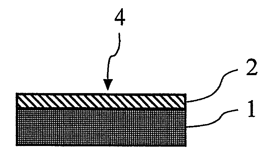
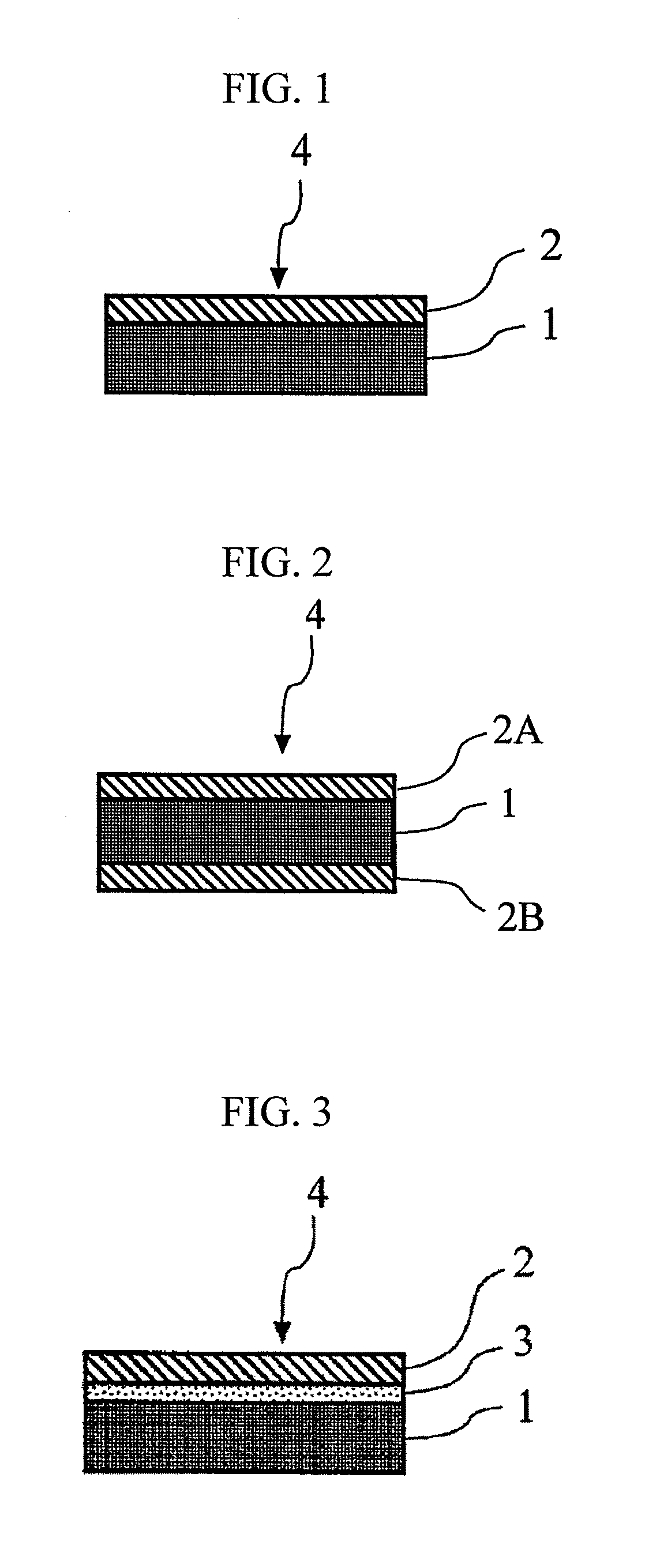
[0087]The obtained coating solution 1 was applied on a polyimide film having a thickness of 13 μm (trade name: “Kapton 50H”, manufactured by DuPont-Toray Co., Ltd.) so that the thickness after drying was 10 μm, and drying the solution, to thereby obtain a pressure-sensitive adhesive tape 1.

example 2

[0088]A pressure-sensitive adhesive tape 2 was obtained in the same manner as in Example 1, except that a polyimide film (trade name: “Kapton 100H”, manufactured by DuPont-Toray Co., Ltd.) having a thickness of 25 μm was used instead of the polyimide film (trade name: “Kapton 50H”, manufactured by DuPont-Toray Co., Ltd.) having a thickness of 13 μm.

example 3

[0089]A pressure-sensitive adhesive tape 3 was obtained in the same manner as in Example 1, except that a polyimide film (trade name: “Kapton 200H”, manufactured by DuPont-Toray Co., Ltd.) having a thickness of 50 μm was used instead of the polyimide film (trade name: “Kapton 50H”, manufactured by DuPont-Toray Co., Ltd.) having a thickness of 13 μm.


PUM

PropertyMeasurementUnit
Temperatureaaaaaaaaaa
Lengthaaaaaaaaaa

Abstract

The present invention relates to a pressure-sensitive adhesive tape for protecting an electrode plate, containing: a substrate, and a pressure-sensitive adhesive layer provided on at least one side of a the substrate, in which the pressure-sensitive adhesive tape has a piercing resistance, obtained by the following calculation method, of 300 gf·mm or more; and has a heat shrinkage ratio, when heating is performed at 260° C. for 1 hour, of 1.0% or less in both of TD (width) direction and MD (length) direction, and in which the calculation method contains fixing the pressure-sensitive adhesive tape to a fixing plate in which a circular hole having a diameter of 11.28 mm is formed, piercing a needle of which the end of has a curvature radius of 0.5 mm to the pressure-sensitive adhesive tape at a speed of 2 mm/s under condition of 23±2° C., and measuring a maximum load (gf) and a maximum elongation (mm) of the pressure-sensitive adhesive tape when the needle penetrates the pressure-sensitive adhesive tape; and the piercing resistance is calculated by the following equation (1):
Piercing resistance=[Maximum load (gf)]×[Maximum elongation (mm) of the pressure-sensitive adhesive tape]×½  (1).

Description

TECHNICAL FIELD[0001]The present invention relates to a pressure-sensitive adhesive tape for protecting an electrode plate, and more particularly, to a pressure-sensitive adhesive tape that is used for preventing a short-circuit by attaching the tape to an inside of the battery such as a lithium ion battery.[0002]Recently, a secondary battery such as a lithium ion battery is indispensable as an electric source of mobile devices such as a cellular phone or a laptop computer. In addition, since the lithium ion battery has high capacity and lightweight, the lithium ion battery is expected to be used as a battery for electric vehicles, and it has been required to make a higher capacity battery from now on.[0003]As the capacity of the lithium ion battery becomes higher, especially in the case of the winding type battery, the number of windings of the winding electrode plate tends to be increased. Therefore, a thinner separator is mainly used. However, there is a problem that, in the manu...

Claims


Application Information

Patent Timeline
IPC IPC(8): B32B7/12C09J7/38
CPCC09J7/0207Y10T428/28C09J2479/086C09J7/38Y02E60/10C09J7/22C09J7/30C09J2203/33C09J2301/312H01M50/579
Inventor IWATA, JUNKAMITANI, MITSURUHANAI, HIROOMI
Owner NITTO DENKO CORP
Why Eureka
Try Eureka