
System and method for identifying breathing transitions

a technology of breathing transition and identification system, which is applied in the field of respiratory state transition identification, can solve the problems of compromising the interface between the patient and the pressure generator, affecting the identification of breathing transitions in the respiration of the subject, and expensive conventional mechanisms for measuring and/or estimating flow at or near the airway of the subject, so as to reduce false identification

Active Publication Date: 2017-03-14
KONINK PHILIPS ELECTRONICS NV
View PDF12 Cites 10 Cited by
  • Summary
  • Abstract
  • Description
  • Claims
  • Application Information

AI Technical Summary

Benefits of technology

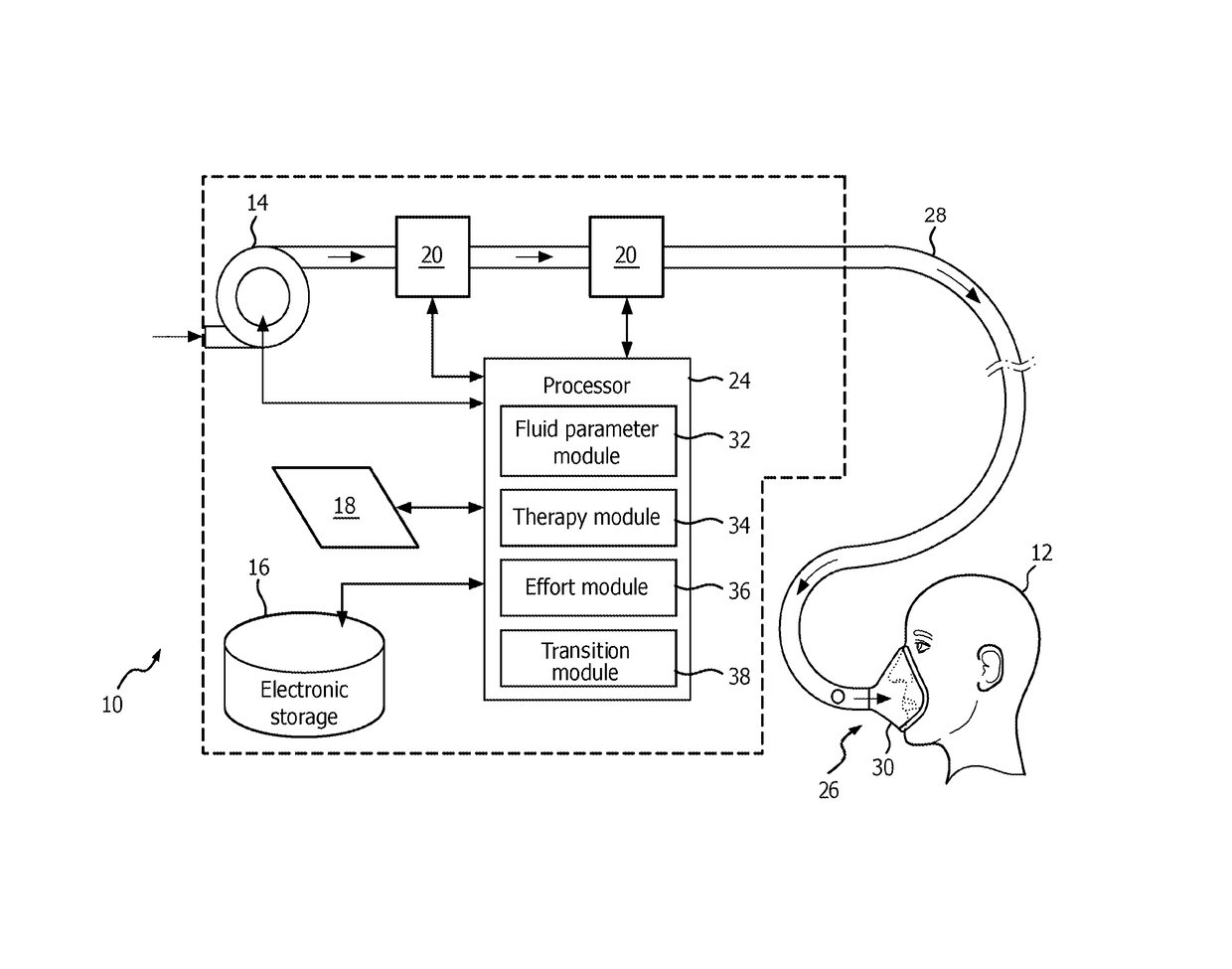
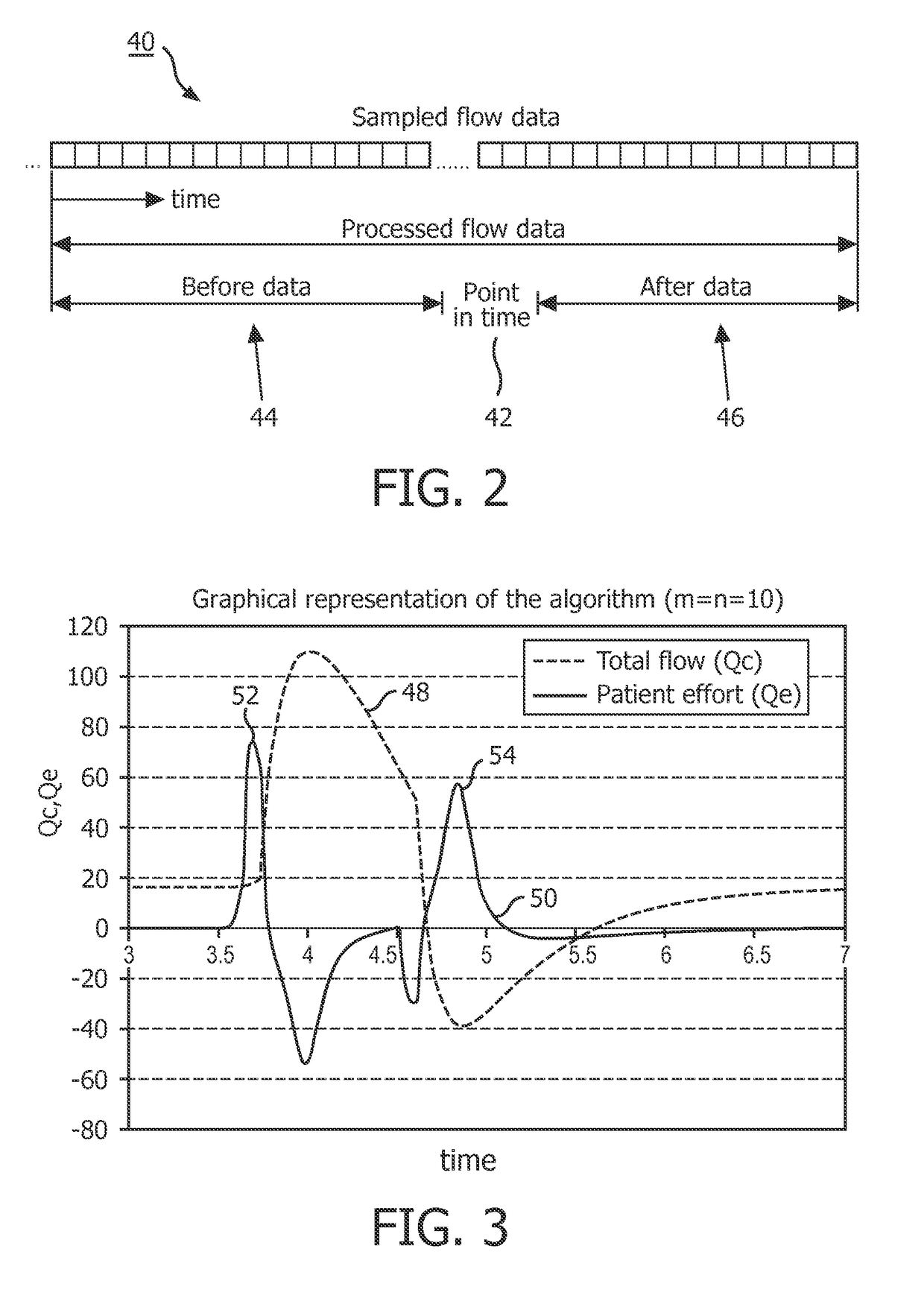
[0008]One aspect of the invention relates to a system and / or method for the identification of transitions in respiratory state without relying on measurement or estimation of flow at or near the airway of subject. Transitions in respiratory state may be identified based on changes in the first time derivative of flow at or near the airway of the subject. In some embodiments, an effort parameter is determined that approximates the second time derivative of flow. Based on comparisons of the effort parameter to a threshold, transitions in respiratory state are identified. The threshold may be dynamic to reduce false identifications of transitions in respiratory state.

Problems solved by technology

Conventional mechanisms for measuring and / or estimating flow at or near the airway of a subject may be costly (in terms of hardware requirements), imprecise, inaccurate and complicate the interface between the patient and the pressure generator.
As such, identifications of breathing transitions in the respiration of a subject are compromised by these drawbacks associated with the direct flow measurement proximal to the patient.
These methods of estimations and compensations are burdened with assumptions regarding the physical characteristics of the patient circuit and require an accurate estimation of leak and other losses.
However, this method, apart from being costly and bulky, fails when leak is present (e.g., when a tracheostomy cuff deflates).
When measurements are done near the respiratory device, complex estimation algorithms are necessary to compensate for losses and leak.
These methods fail when these losses are unpredictable or deviate from the assumptions and models used for fluid parameter estimation, e.g., when a caregiver administers a breathing treatment such as a nebulized flow of gas within the patient circuit or said caregiver adds or removes lossy components from a standard assumed patient circuit.

Method used


Image

  • System and method for identifying breathing transitions
  • System and method for identifying breathing transitions
  • System and method for identifying breathing transitions

Examples


Embodiment Construction

[0018]As used herein, the singular form of “a”, “an”, and “the” include plural references unless the context clearly dictates otherwise. As used herein, the statement that two or more parts or components are “coupled” shall mean that the parts are joined or operate together either directly or indirectly, i.e., through one or more intermediate parts or components, so long as a link occurs. As used herein, “directly coupled” means that two elements are directly in contact with each other. As used herein, “fixedly coupled” or “fixed” means that two components are coupled so as to move as one while maintaining a constant orientation relative to each other.

[0019]As used herein, the word “unitary” means a component is created as a single piece or unit. That is, a component that includes pieces that are created separately and then coupled together as a unit is not a “unitary” component or body. As employed herein, the statement that two or more parts or components “engage” one another shal...


PUM


Abstract

A pressurized flow of breathable gas is delivered to the airway of a subject in accordance with a therapy regimen. One or more fluid parameters of the pressurized flow of breathable gas are adjusted based on the therapy regimen. The therapy regimen dictates that such adjustments be made based on the respiratory state of the subject. Transitions in respiratory state are identified without relying on measurement or estimation of flow at or near the airway of subject. Transitions in respiratory state are identified based on changes in the first time derivative of flow at or near the airway of the subject. In one embodiment, an effort parameter is determined that approximates the second time derivative of flow. Based on comparisons of the effort parameter to a dynamic threshold, transitions in respiratory state are identified.

Description

CROSS-REFERENCE TO RELATED APPLICATIONS[0001]This patent application claims the priority benefit under 35 U.S.C. §371 of international patent application no. PCT / IB2011 / 053849, filed Sep. 2, 2011, which claims the priority benefit under 35 U.S.C. §119(e) of U.S. Provisional Application No. 61 / 381,553 filed on Sep. 10, 2010, the contents of which are herein incorporated by reference.BACKGROUND OF THE INVENTION[0002]1. Field of the Invention[0003]The invention relates to the problem of respiratory state transition identification (e.g., accurate and / or systematic detection of the beginning or conclusion of a subjects inspiration or expiration). Proper and synchronous identification of respiratory state transitions are used to adjust or initiate a pressurized flow of breathable gas delivered to the airway of a subject in accordance with a therapy regimen.[0004]2. Description of the Related Art[0005]Systems that deliver pressurized flow of breathable gas to the airway of subjects are kno...

Claims


Application Information

Patent Timeline
Patent Type & Authority Patents(United States)
IPC IPC(8): A61M16/00A61B5/00A61M16/04A61M16/16A61M16/08A61M16/06A61M16/10
CPCA61M16/0057A61M16/0051A61M16/04A61M16/0666A61M16/0875A61M16/161A61M2016/0027A61M2016/0036A61M2016/102A61M2205/332A61M2205/3365A61M2205/3368A61M2205/3375A61M2205/3569A61M2205/3584A61M2205/3592A61M2205/505A61M2205/52A61M2016/0021A61M16/1065A61M16/026
Inventor TRUSCHEL, WILLIAM A.MAHADEVAN, ANANDI
Owner KONINK PHILIPS ELECTRONICS NV
Learn More