
Slotted waveguide antenna with metamaterial structures

a waveguide antenna and metamaterial technology, applied in the direction of slot antennas, linear waveguide fed arrays, antennas, etc., can solve the problems of mechanical instability, increase weight, detrimental to the gain of the swa, etc., and achieve the effect of negative effective permittivity, negative effective permeability, and negative effective permeability

Active Publication Date: 2017-03-14
COBHAM ADVANCED ELECTRONICS SOLUTIONS
View PDF19 Cites 8 Cited by
  • Summary
  • Abstract
  • Description
  • Claims
  • Application Information

AI Technical Summary

Benefits of technology

The present patent relates to a system, apparatus, and antenna system that use a slotted waveguide antenna and metamaterial structure. The metamaterial structure exhibits negative effective permittivity and permeability for the operating frequency range. The system includes a waveguide antenna and a metamaterial structure positioned external to the waveguide. The metamaterial structure includes a split ring resonator, substrate, and wire structure. The wire structure includes a first portion, second portion, and third portion. The second and third portions are coupled between the first portion and the second portion. The first and third portions are oriented parallel to each other and perpendicular to the first portion. The dimension of at least one of the first and third portions is related to the operating frequency range. The technical effect of this patent is to provide a system that enhances the performance of the slotted waveguide antenna by using a metamaterial structure that exhibits negative effective permittivity and permeability for the operating frequency range.

Problems solved by technology

Increasing size may result in increased weight and / or mechanical instability.
Dielectric materials can be lossy (i.e., non-zero loss tangent) and, thus, may detrimentally affect the gain of the SWA.

Method used


Image

  • Slotted waveguide antenna with metamaterial structures
  • Slotted waveguide antenna with metamaterial structures
  • Slotted waveguide antenna with metamaterial structures

Examples


Embodiment Construction

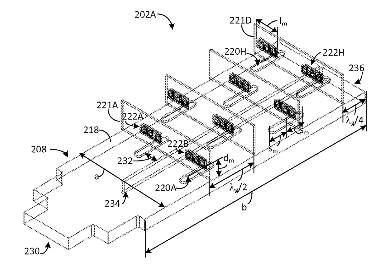
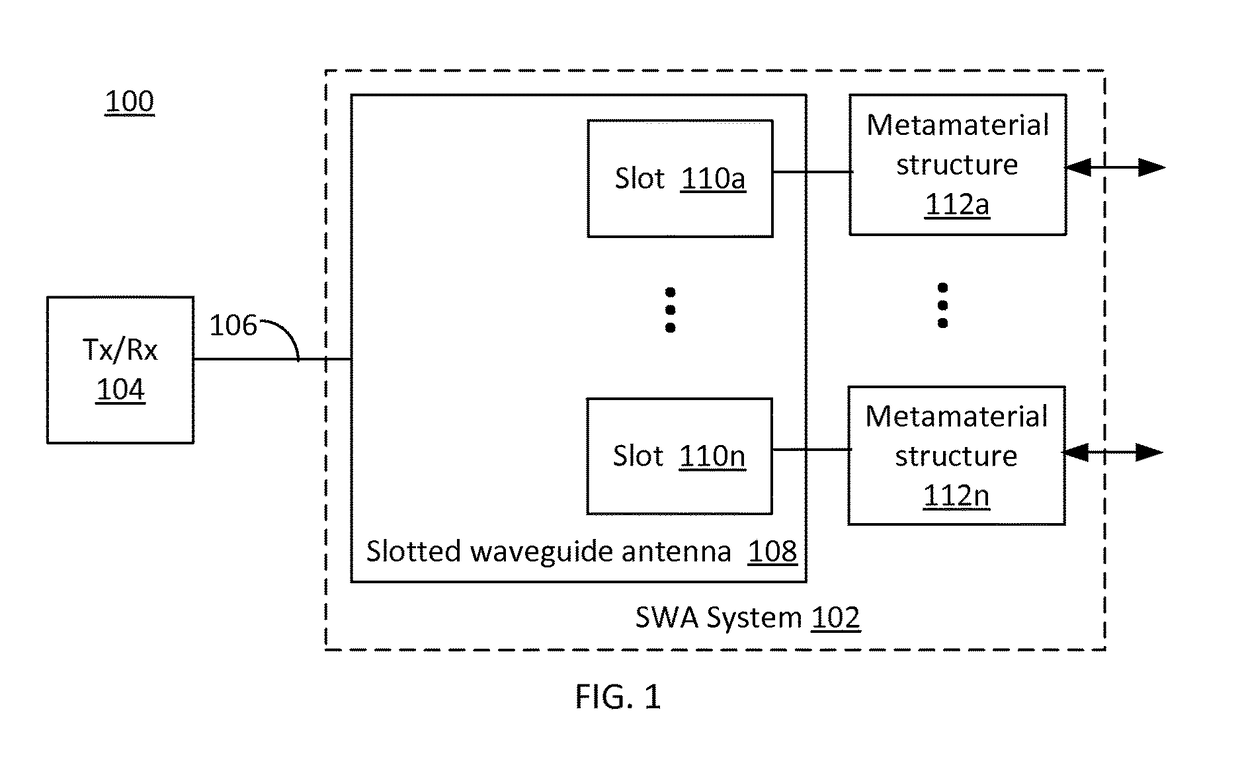
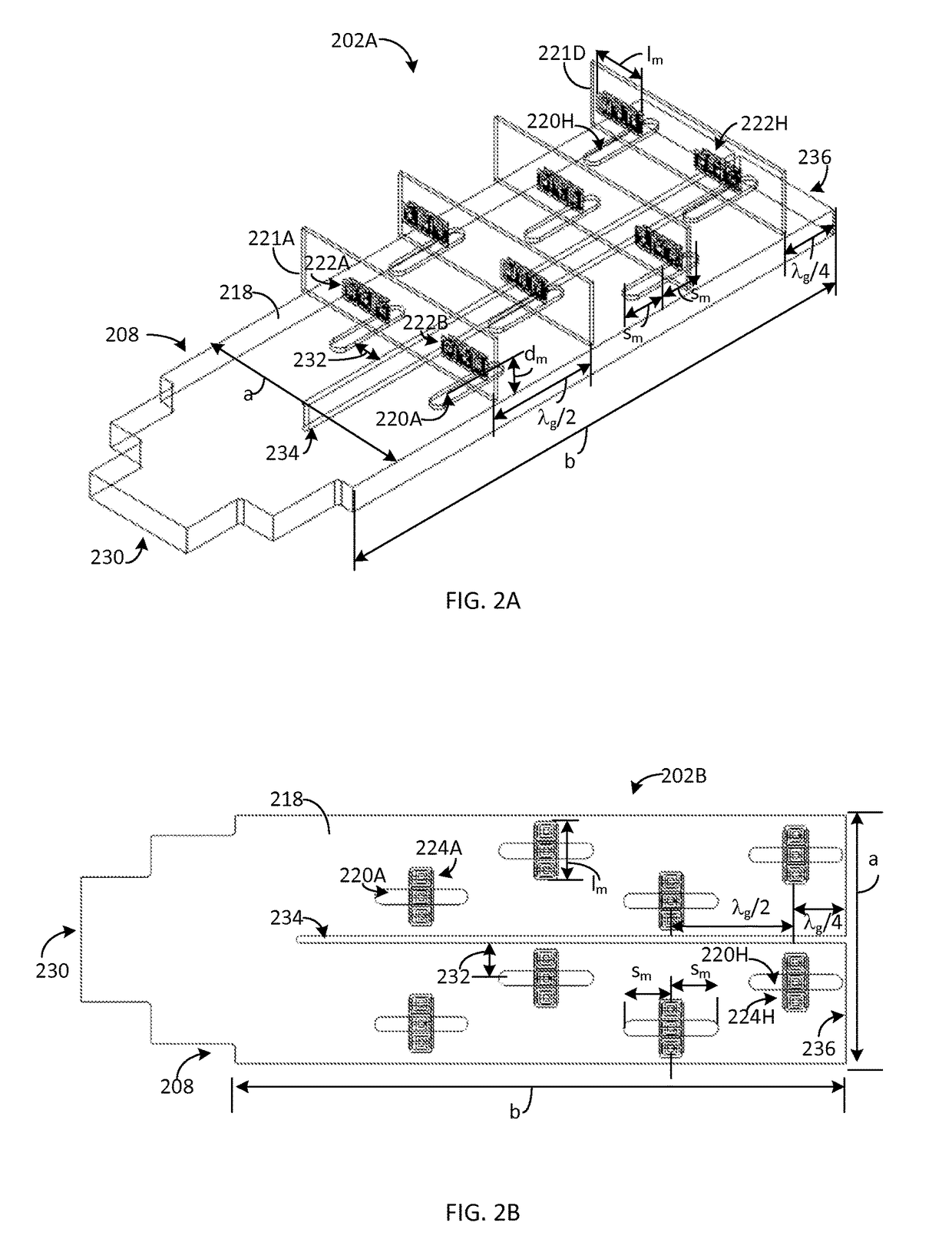
[0022]Generally, this disclosure describes a slotted waveguide antenna system and method. The slotted waveguide antenna system includes a slotted waveguide antenna (SWA) and a plurality of metamaterial structures positioned external to the SWA. The metamaterial structures are configured to enhance one or more performance characteristic(s) of the SWA. The performance characteristics include directivity, gain, bandwidth, beamwidth and / or VSWR (voltage standing wave ratio). Thus, performance of the SWA may be enhanced without increasing a size of the SWA and / or the size of the SWA may be decreased while maintaining performance characteristic(s) by the addition of the metamaterial structures.

[0023]The SWA includes a rectangular waveguide with a plurality of slots defined in a surface of the SWA. A plurality of metamaterial structures may be positioned external to the SWA, with a respective metamaterial structure positioned relative to each slot. In an embodiment, the metamaterial struct...


PUM


Abstract

The present disclosure relates to a slotted waveguide antenna system. The slotted waveguide antenna system includes a waveguide that includes a first surface and a plurality of slots defined in the first surface and a metamaterial structure positioned external to the waveguide. The metamaterial structure is configured to exhibit a negative effective permittivity and a negative effective permeability for an operating frequency range. The metamaterial structure includes a split ring resonator, a substrate and a wire structure. The wire structure includes a first portion, a second portion and a third portion, the second portion coupled between the first portion and the second portion, the first portion oriented parallel to the third portion, the second portion oriented perpendicular to the first portion and the third portion. A dimension of at least one of the first portion and the third portion is related to the operating frequency range.

Description

CROSS-REFERENCE TO RELATED APPLICATIONS[0001]Not applicableSTATEMENT REGARDING FEDERALLY SPONSORED RESEARCH OR DEVELOPMENT[0002]Not applicableTHE NAMES OF THE PARTIES TO A JOINT RESEARCH AGREEMENT[0003]Not applicableINCORPORATION-BY-REFERENCE OF MATERIAL SUBMITTED ON A COMPACT DISC[0004]Not applicableBACKGROUND[0005]Field of the Disclosure[0006]This disclosure relates to a slotted waveguide antenna, in particular to a slotted waveguide antenna with metamaterial structures.[0007]Description of Related Art[0008]Generally, slotted waveguide antennas (SWAs) include a rectangular waveguide with slots formed in at least one surface. Electromagnetic energy may be provided to the SWA by a transmission line and / or another waveguide configured to couple a transmitter and / or receiver to the SWA. For example, SWAs may be used in navigational radar applications. SWAs may be configured to operate at one or more frequencies between about 1 gigahertz (GHz) and about 26 GHz.[0009]SWA antenna charact...

Claims


Application Information

Patent Timeline
IPC IPC(8): H01Q13/18H01Q15/00
CPCH01Q13/18H01Q15/0086H01Q21/005
Inventor VALAYIL, MINU K.
Owner COBHAM ADVANCED ELECTRONICS SOLUTIONS
Learn More