Elastic roller with needle-shaped filler and fixing device

a technology of filler and filler, which is applied in the direction of electrographic process apparatus, instruments, optics, etc., can solve the problems of accelerating “temperature rise in a non-, accelerating temperature rise, preventing temperature rise, etc., to maintain the shape, prevent temperature rise, and maintain the effect of rapid start-up

Active Publication Date: 2017-03-28
CANON KK
View PDF8 Cites 3 Cited by
  • Summary
  • Abstract
  • Description
  • Claims
  • Application Information

AI Technical Summary

Benefits of technology

[0009]One aspect of the present invention is directed to providing an elastic roller that can keep its shape stable for a long period of time while preventing temperature rise in a non-sheet-passing area and maintaining quick start-up. Another aspect of the present invention is directed to providing a fixing device that can efficiently heat a recording medium while minimizing temperature rise in a non-sheet-passing area and that can stably form high-quality images.

Problems solved by technology

Such a pressing member impedes thermal conduction.
The pressing member that impedes thermal conduction, however, has a disadvantage in that while a recording medium is passed through the nip portion, the pressing member accelerates temperature rise in an area of the pressing member with which a recording medium does not come into contact (hereinafter this area is referred to as a “non-sheet-passing area”), more specifically, in widthwise both end portions of the pressing member, that is, it accelerates “temperature rise in a non-sheet-passing area”.
The temperature rise in a non-sheet-passing area may degrade the quality or distort the shape of the heating member or the pressing member of the fixing device.
Moreover, when the nip portion that is in an excessively heated state after small-size recording media are passed therethrough receives a larger-sized recording medium, excessively molten toner may cause offset.

Method used


Image

  • Elastic roller with needle-shaped filler and fixing device
  • Elastic roller with needle-shaped filler and fixing device
  • Elastic roller with needle-shaped filler and fixing device

Examples


example 1

[0125](1-1)

[0126]The PFA tube was fixed in the cylindrical mold by a well-known method in the extended state. The PFA tube and the cylindrical mold were visually confirmed as being closely attached to each other.

[0127](1-2)

[0128]A primer (trade name of DY39-067, manufactured by Dow Corning Toray Co., Ltd.) was applied to the inner surface of the PFA tube described in (1-1) by a well-known method and left as it is at the room temperature for a predetermined period of time so as to be dried.

[0129](1-3)

[0130]A primer (trade name of DY35-051, manufactured by Dow Corning Toray Co., Ltd.) was applied to the mandrel by a well-known method, fired for a predetermined period of time at 200° C., and then left so as to be cooled.

[0131](1-4)

[0132]The nozzle was attached to the pipe of the device illustrated in FIG. 4 using an adaptor and the mandrel described in (1-3) was perpendicularly fixed to the mandrel fastening portion of the nozzle. The cylindrical mold to which the PFA tube described in...

example 2 to example 8

[0141]Elastic rollers were obtained in the same manner as described in Example 1, except that the mandrel, the type of emulsion, and the injection rate of the emulsion were appropriately selected and the emulsion was injected while the thickness of the cavity, the average flow rate of the emulsion, and the viscosity of the emulsion were changed in accordance with the conditions described in Table 2.

[0142]The average flow rate (mm / s) was calculated by the following formula (2):

average flow rate (mm / s)=injection volume of liquid compound into cavity per minute (mm3 / s) / area of cross section of cavity (mm2)  Formula (2).

[0143]Elastic rollers were obtained in the same manner as described in Example 1, except that the mold, the mandrel, the type of emulsion, and the injection rate of the emulsion were appropriately selected and the emulsion was injected while the thickness of the cavity, the injection rate, and the viscosity of the emulsion were changed in accordance with the conditions d...


PUM


Abstract

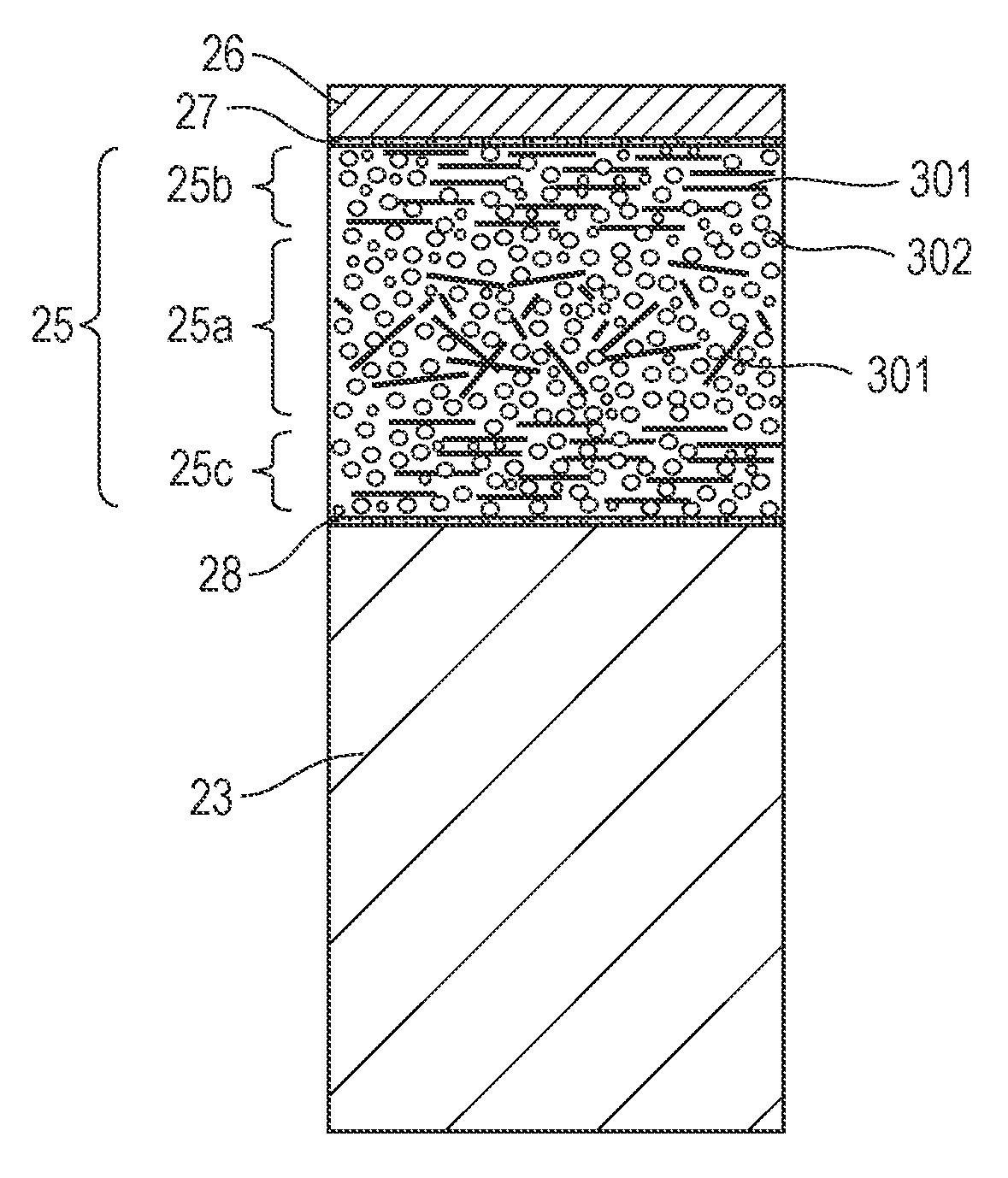
An elastic layer includes a needle-shaped filler and a void and has a porosity of 20 vol % or more and 60 vol % or less. The elastic layer contains a first area and a second area. The first area extends from a surface of the elastic layer opposite to a surface facing the mandrel toward the mandrel and has a thickness of 30% of the thickness of the elastic layer. The second area is a central area in a thickness direction of the elastic layer and has a thickness of 40% of the thickness of the elastic layer. The needle-shaped filler in the second area has an orientation degree of 50% or lower. The needle-shaped filler in the first area has an orientation degree higher than that of the needle-shaped filler in the second area.

Description

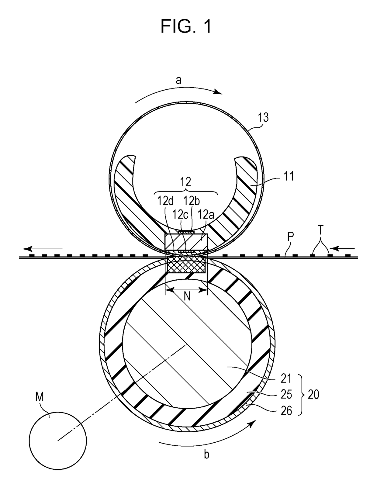
BACKGROUND OF THE INVENTION[0001]Field of the Invention[0002]The invention relates to a fixing device mounted on an image forming device such as an electrophotographic copying device or a printer, an elastic roller included in this fixing device, and the fixing device including the elastic roller.[0003]Description of the Related Art[0004]A fixing device included in an electrophotographic toner-image forming device includes a heating member, which is heated by a heater and heats an image by coming into contact with an image carrying surface of a recording medium, and a pressing member disposed opposite to the heating member and forming a fixing nip (hereinafter referred to as a “nip portion”) in cooperation with the heating member.[0005]In recent years, techniques for enhancing heating efficiency of a fixing device and reducing the start-up time (warm-up time) of a fixing device have been developed for energy saving. One example of such techniques is a use of porous silicone rubber h...

Claims


Application Information

Patent Timeline
Patent Type & Authority Patents(United States)
IPC IPC(8): G03G15/20
CPCG03G15/206G03G15/2089G03G2215/2035
Inventor ARAI, YUTAKASUZUKI, TAKESHIMIURA, JUNTAKADA, SHIGEAKINAKAYAMA, TOSHINORIAKIYAMA, NAOKIMATSUURA, DAIGOMIYAHARA, YASUHIROASAKA, AKESHITAMURA, SHUICHIMATSUNAKA, KATSUHISATAKAHASHI, SHINSUKESUGIMOTO, HIROTO
Owner CANON KK
Why Eureka
Try Eureka