Electronic switching device and system

a technology of electronic switching and ground straps, which is applied in the direction of electronic switching, casings with connectors, pcbs, etc., can solve the problems of inefficient use of space by conventional wiring devices, inconvenient installation methods, and time-consuming, and thus cost-effective, and avoid the effect of affecting the operation of conventional wiring devices

Active Publication Date: 2017-03-28
PASS SEYMOUR
View PDF10 Cites 28 Cited by
  • Summary
  • Abstract
  • Description
  • Claims
  • Application Information

AI Technical Summary

Problems solved by technology

There are several drawbacks associated with conventional installation methods and conventional wiring devices.
Conventional wiring devices often do not make efficient use of space due to their one-size-fits-all device box designs.
Mounting the ground strap of an electrical wiring device to the device box is tedious, time consuming, and therefore costly.
In multi-gang installations, the finished look is often ragged because the electrical devices and the cover plates are not in alignment.
Retrofitting an installation can also be problematic from a finished look standpoint because the device box or an old work box may not be precisely aligned to the plane of the wall surface.
Moreover, the wall surface itself may be uneven.
Thus, a homeowner may inadvisably remove the faceplate cover from an energized wiring device and inadvertently become exposed to a shock hazard from the “hot” electrical wiring.
One drawback to these types of switches is that a light must turned ON / OFF from one location.
Some of the drawbacks associated with relay switches relate to degradation, fatigue, undesired arcing and excessive leakage current to ground.
Again, the homeowner may inadvisably attempt to replace the existing electrical switch with a new device and become exposed to a shock hazard from the “hot” electrical wiring.

Method used


Image

  • Electronic switching device and system
  • Electronic switching device and system
  • Electronic switching device and system

Examples


Embodiment Construction

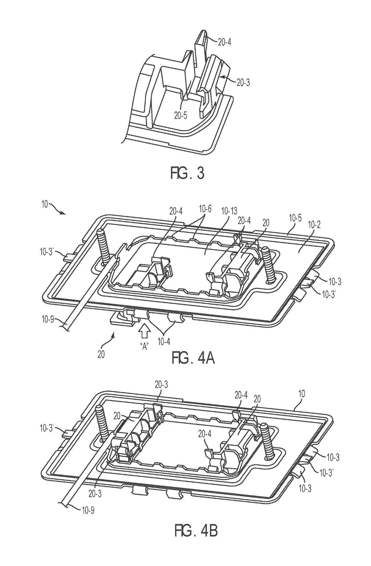
[0041]Reference will now be made in detail to the present exemplary embodiments of the invention, examples of which are illustrated in the accompanying drawings. Wherever possible, the same reference numbers will be used throughout the drawings to refer to the same or like parts. An exemplary embodiment of the frame is shown in FIGS. 1-4, and is designated throughout as reference number 10. An exemplary embodiment of the electrical switch device of the present invention is shown in FIG. 6, and is designated generally throughout by reference numeral 100. An exemplary embodiment of the framing system that includes the frame member, frame components, and switch 100 is shown in FIGS. 5A-5C and is designated generally throughout by reference numeral 500.

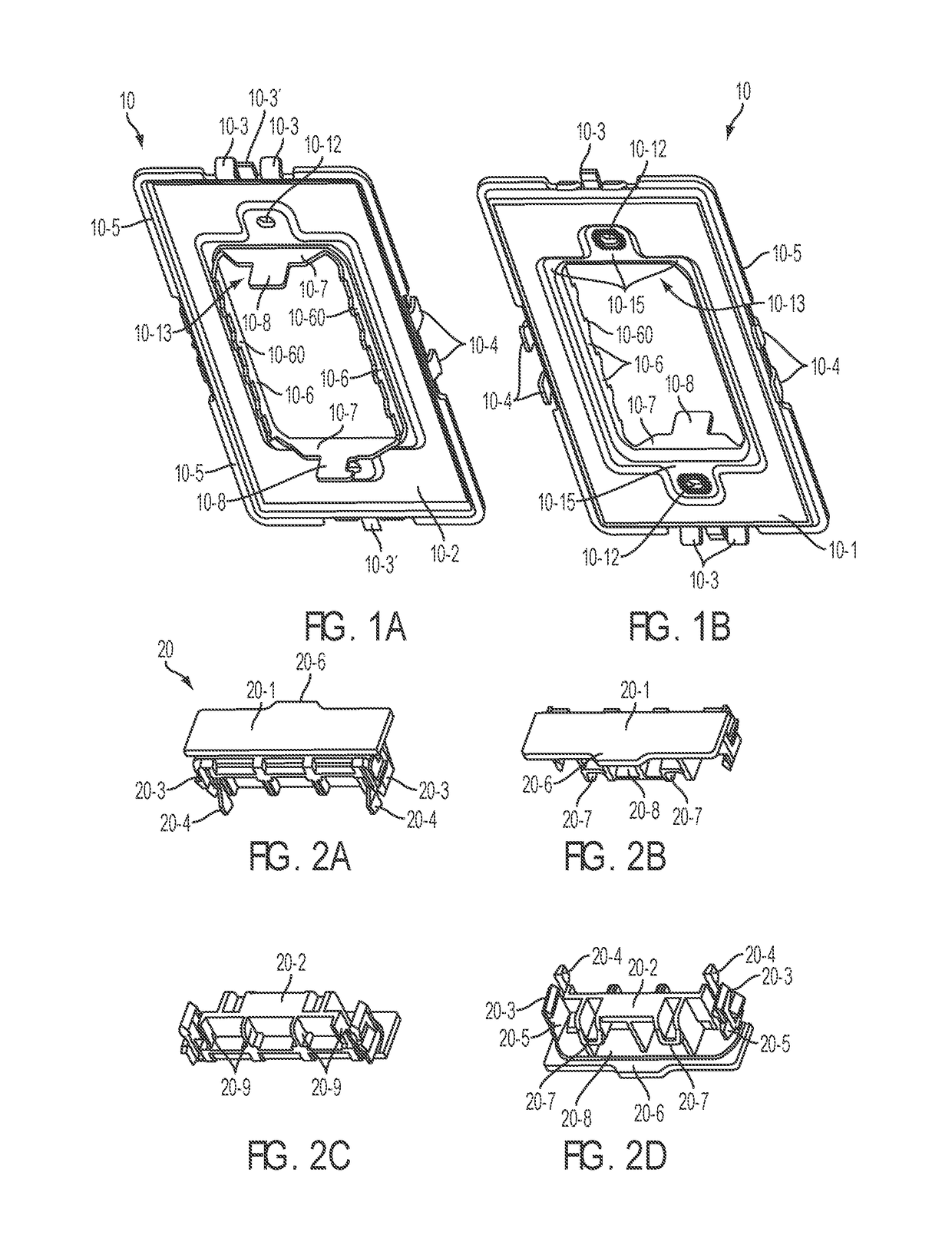
[0042]As embodied herein, and depicted in FIGS. 1A-1B perspective views of a frame member in accordance with the present invention are disclosed. FIG. 1A is directed to the rear side 10-2 of the frame member 10 and FIG. 1B is directed to ...


PUM


Abstract

The present invention is directed to an electronic switch device that includes a front cover assembly having a user interface, a back body assembly, and a plurality of terminals configured to be coupled to an AC power source and the load. A circuit assembly is coupled to the plurality of terminals. The circuit assembly includes a relay switch having a commutator and a set of contacts. The relay switch is characterized by a predetermined commutator period, the predetermined commutator period being substantially the commutator travel time between the set of contacts during a relay switch actuation. The circuit assembly further includes an actuation circuit configured to provide a constant current actuation signal that energizes the relay switch in response to an input stimulus via the user interface such that an end of the predetermined commutator period substantially coincides with a predetermined point in an AC power cycle.

Description

BACKGROUND OF THE INVENTION[0001]1. Field of the Invention[0002]The present invention relates generally to electrical devices, and particularly to electrical switch devices.[0003]2. Technical Background[0004]The conventional method for installing electrical circuits includes a rough-in phase and a finish phase. In the rough-in phase, conduit or cable is disposed throughout the structure in accordance with the building plans. Junction boxes are installed at appropriate locations to house electrical connection points where two or more conductors are spliced together. Device boxes are installed throughout the structure where electrical service is desired. After the boxes are placed, the electrical wires are pulled through the conduits (if provided) and all of the circuits are bonded.[0005]After the “rough-in” phase has been completed, the electrical wiring devices are terminated, i.e., they are electrically connected to the wire leads. This part of the installation process is typically...

Claims


Application Information

Patent Timeline
Patent Type & Authority Patents(United States)
IPC IPC(8): H01H9/56H01H47/22H03K17/96H01H9/18H01H13/14
CPCH01H9/56H01H47/22H03K17/962H01H9/182H01H13/14H01H2239/07H03K2217/960755Y10T307/944H02G3/081H05K5/0026H05K5/03
Inventor HAINES, JOSHUA P.ROHMER, RICHARD MSAVICKI, JR., GERALD R.
Owner PASS SEYMOUR
Why Eureka
Try Eureka